Components
F60: Idle switch
G4: Reference point sensor
G6: Fuel pump
G28: Reference Sensor
G39: Oxygen sensor I
G40: Hall Sensor
G61: Knock sensor I
G62: Engine Coolant Temperature (ECT) sensor
G66: Knock sensor II
G69: Throttle valve potentiometer
G70: Mass Air Flow (MAF) sensor
G74: CO Potentiometer
G98: Exhaust Gas Recirculation (EGR) temperature sensor
G108: Oxygen sensor II
J176: Fuel pump relay
J192: Engine Control Module (ECM)
N: Ignition coil for cylinders 1 and 6
N18: EGR frequency valve
N30: Fuel injector, cylinder 1
N31: Fuel injector, cylinder 2
N32: Fuel injector, cylinder 3
N33: Fuel injector, cylinder 4
N71: Idle Air Control (IAC) valve
N80: EVAP carbon canister frequency valve
N83: Fuel injector, cylinder 5
N84: Fuel injector, cylinder 6
N122: Power stage for ignition coils
N128: Ignition coil for cylinders 2 and 4
N156: Intake manifold change-over valve
N158: Ignition coil for cylinders 3 and 5
P: Spark plug connector (6x)
Q: Spark plug (6x)
S17: Fuse for G6
S19: Fuse for diagnostic connector
S72: Circuit breaker for N30, N31, N32, N33, N83, and N84
S73: Circuit breaker for G39, G108, N18, N80, and N156
S74: Circuit breaker for G70 and G74
Additional Signals
B8: Throttle valve signal (not pictured)
B9: Road speed signal (not pictured)
B10: Engine speed signal (not pictured)
B11: Fuel consumption signal (not pictured)
B12: Shift lever position signal (not pictured)
B13: Shift point signal (not pictured)
C10: A/C compressor signal (not pictured)
C12: Diagnostic signal for Rapid Data (K circuit)
C13: Diagnostic signal for Rapid Data (L circuit)
C14: Flash code signal
|
|
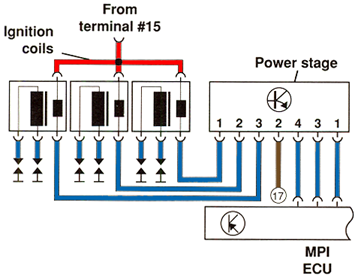
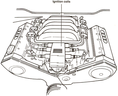
Ignition coils N, N128, and N158 with Power Stage N122
|
|
The ignition system for the V6 is distributorless. Since there are no moving parts,
no noise is generated to interfere with the knock sensor system. The system is also
easier to maintain as no routine adjustments are necessary.
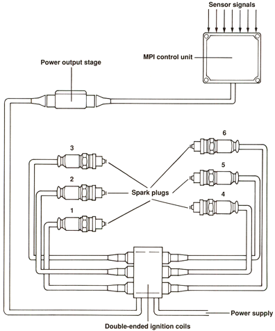
The ignition part of the MPI system consists of the following:
- Power output stage
- Three double-ended ignition coils
- MPI control unit
|
|
|
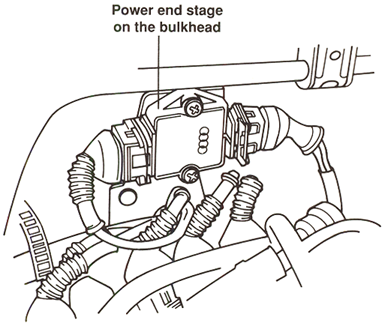
The MPI control unit operates each double-ended ignition coil via the power output stage
(power stage N122). The power stage is located on the bulkhead behind the engine.
|
|
|
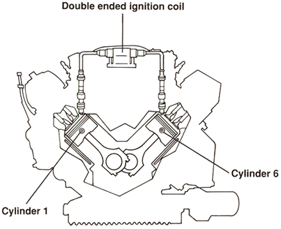
When the ignition coil fires, spark is supplied to two cylinders at the same time. One
plug fires during the compression stroke and ignites the fuel mixture. At the same
time, the other plug fires during the exhaust stroke.
|
|
For example, when the spark plug for cylinder #1 fires on its compression stroke,
the spark plug for cylinder #6 fires during its exhaust stroke.
After 360° of crankshaft revolution, cylinder #6 is in the compression stroke and
cylinder #1 is in the exhaust stroke.
The same procedure is followed for cylinders 2&4 and 3&5.
|
|
The automatic transmission ECU signals each gearshift to the MPI control unit. The MPI
control unit responds by retarding the ignition timing point during the gear change.
This reduces engine torque during shift, making gear changes more comfortable.
Substitute Function
There are no substitute functions for the ignition coils.
If an ignition coil, spark plug wire, or spark plug should fail, the corresponding
injectors are switched off as well as the oxygen sensor control and full throttle
enrichment functions.
|
|