
| |
Having said that:
These instructions assume:
- You have a Malfunction Indicator Lamp (MIL) and that it is operational
- Your car has the 12v V6 engine. These codes may not accurately translate to different OBD-I versions, such as those used with the 5 cylinder engine.
If you do not have an operational MIL (commonly known as a 'check engine light' ... it's a picture of an engine with a lightning bolt through it, and should be one of only a couple of amber warning lights), you need to use the test light method.
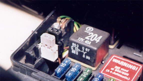
Now find the connectors you need. They are located in the fusebox, which on most models is under the hood behind the firewall, on the driver's side. Open the fusebox and look for a pair of two-pin connectors in corner:
If the engine runs, you should try to extract and view the trouble codes with the engine running. If the engine will not run, crank the engine for 5 or 6 seconds (never crank the engine for more than 10 seconds!) and leave the key in the 'on' position. Now you need to make a connection between one pin in each connector. In the picture below, carefully note the position, shape, and orientation of the two data link connectors: one is white, and the other is black. They both have keyed edges, but they are keyed differently. Their location in the fuse box varies between models, as does the orientation of the fuse box itself, so look closely at the actual connectors rather than where they are in the box. Connecting the wrong pair of pins is unlikely to cause any damage, but you might inadvertantly clear the codes (so you'll have to wait for them to appear again). You should connect the two pins for 3 seconds using a short length of wire (I usually use a bent paper clip):
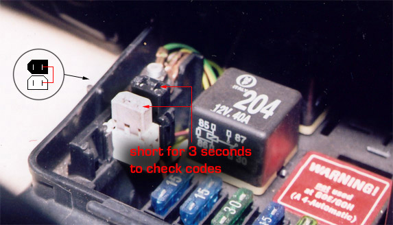
Thanks to Kent McLean for correcting this photo
Once you have removed the wire, immediately go look at the instrument cluster, and watch the MIL. It will start blinking a sequence -- each trouble code will be comprised of 4 groups of flashes with a maximum of 4 flashes per group. Between each group of four (one code), there will be a delay of about 2.5 seconds before the next code starts to come out:
If no trouble codes were present, the code "4444" will display. If the engine is not running when you view the codes, the first code you will see will be 2111. This code (engine speed sensor) can safely be ignored if the engine is not running when the codes are pulled. When all of the codes are displayed, the code 0000 (end of output) is displayed -- 0000 is represented by four 2.5 second flashes at 2.5 second intervals. Once this has displayed, you can decode the 4-digit code to see what the problem is by consulting the table below.
On some 1992-1993 models (those with the MMS200 ECU), if you have multiple DTCs stored you need to momentarily connect the pins (the ones you just shorted) to advance from the currently displayed code before the next code will be displayed. (Thanks to John Dolen for pointing this out!)
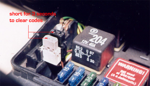
When you have looked at the codes, fixed the problems, and are ready to test your work, you can clear all of the DTCs by shorting the other two pins on the two connectors for three seconds:
4444
No DTC recognized.
0000
Display ends.
1231
Vehicle Speed Sensor.
2111
Engine Speed Sensor.
2112
Crankshaft Position Sensor.
2113
Camshaft Position Sensor.
2121
Closed Throttle Position Switch.
2212
Throttle Position Sensor.
2242
CO Fuel Trim Potentiometer.
2312
Engine Coolant Temperature Sensor [G62].
2142
Knock Sensor 1.
2342
Heated Oxygen Sensor 1 [G39].
2233
Mass Air Flow Sensor Reference Voltage.
2234
ECM Supply Voltage.
2141
Knock Sensor Control 1.
2143
Knock Sensor Control 2.
2341
Oxygen Sensor Control 1.
2144
Knock Sensor 2.
2324
Mass Air Flow Sensor.
2331
Oxygen Sensor Control 2.
2332
Heated Oxygen Sensor 2 [G108].
2411
EGR System.
4332
Ignition Output 1, 2, or 3.
4343
EVAP Canister Purge Regulator Valve [N80].
4411
Injector, Cylinder 1 [N30].
4412
Injector, Cylinder 2 [N31].
4413
Injector, Cylinder 3 [N32].
4414
Injector, Cylinder 4 [N33].
4421
Injector, Cylinder 5 [N83].
4422
Injector, Cylinder 6 [N84].
4431
Idle Air Control Valve [N71].
4432
EGR Vacuum Regulator Solenoid Valve.
1111
Control Module Malfunction.
|
|