Our C4 UrS-car fuel pump is powered by the general 12V power system. In stock form, the power goes from the battery (under the rear seat) to the ignition switch, through the J17 fuel pump relay and then all the way back to the fuel pump (located in the trunk area, behind the battery). Since the wire gauge Audi used isn't the biggest, there are line losses of about 1 V. This may not seem like much but under load, e.g. Wide open throttle (WOT) and big boost, this lost 1 V is very important to the pump's ability to provide enough fuel. The solution is to relay the fuel pump to the battery (about 4 ft from the fuel pump). Sean D. (quattro20v) and I developed a procedure to install such a relay. The result is the write-up below (from Aug 2004):
Background (Interesting or boring, depending on your need for information):
As opposed to some VAG products with two stage fuel pumps (transfer and high pressure), the C4 UrS car has a single stage high pressure
fuel pump located in the fuel tank. As provided by the factory, this pump receives power via a circuitous route: Power from the battery (under the rear seat) is fed forward to the central relay panel under the steering column. Turning the ignition on and starting the engine energizes relay No. 6 in that panel. This sends power from the relay via a green wire to Fuse No. 17, a 20 amp fuse, in the panel on the left end of the dash. From there power goes all the way back to the fuel pump in the trunk by the ski sack in a yellow striped green wire. Based on that route, the car started and 13.5 V or so at the battery, the voltage at the fuel pump is about 12.4 to 12.5 V, i.e. a loss of over one volt. This may not seem important but because the speed of the pump is related to the voltage, the fuel flow and pressure are also related to the voltage at the pump.
While testing the fuel pump voltage while driving (via a tee-connection, 6 ft of wire, the zippered hole in the ski sack, appropriate spade connectors and a digital multimeter), I noted that voltage to the pump dropped (e.g. to 12.2 V) while driving and specifically even more so (down to 11.82 V) under wide open throttle (WOT). Sean did some static testing of the fuel pressures under simulated boost (small compressor connected to the fuel pump regulator vacuum/boost port). He found that, with the engine off, at 11.75 volts (via a switched cable from the + post in the engine bay to the right side of Fuse 17), the boost/fuel pressures were as follows: 0/57,10/65,20/72, 28/80. However, since we are running RS2 turbos and injectors and a new OEM 4.0 Bar (58 psig) fuel pressure regulator, the software wants more from the fuel pump, e.g. 0/58,10/68, 20/78, 28/86. So, since we were potentially short by up to 6 psi of fuel pressure, it was clear that at least there was a possibility that the pinging we were experiencing under WOT was potentially related to low fuel pressures resulting from low voltage at the fuel pump.
To test this more, with the engine off, Sean connected his switched static power lead directly to the battery and tested the simulated boost-controlled fuel pressures again. This resulted in 12.4 V to the fuel pump and boost/fuel pressures of 0/57, 10/65, 20/75 and 28/83. The point is that at the higher simulated boost pressures (20 and 28 psig ), the increased voltage (from 11.75 to 12.4 V) yielded an increase 3 psi. Although this was still 3 psi short of the required 78 and 86 psig, respectively, it showed the potential that directly relaying the fuel pump to the battery would help us to "turbo charge" the fuel pump and get more flow and/or pressure. (NOTE: Dave Forgie talked to a technical rep at Bosch USA who said that low voltages are worse than higher voltages and that the fuel pump could handle up to 16 VDC so the regulated 13.5 V from an alternator should be "no problem").
Based on the above, we (Sean and I) decided to find a way to directly relay the fuel pumps to the battery. As it turned out, it was relatively easy and quite cheap to do so. The results as you will see were quite worth the bother (in our opinion).
The Install
Before you can start an install like this, you need to understand how a relay works: A relay contains a solenoid (electromagnetic and armature) and contact points that are moved by the solenoid. There are typically four pins: two for a low current "trigger" signal (switched power and a ground), a high current line in and a high current line out. When the solenoid is energized by the switched low current "trigger" signal, it pulls the closed which allows high current to flow from the power source to the point of power consumption. The trigger signal in this case is the yellow striped green wire that runs from Fuse 17 to the fuel pump (along with a brown ground from some source). The power source will be a connection to the battery and the point of consumption is the fuel pump.
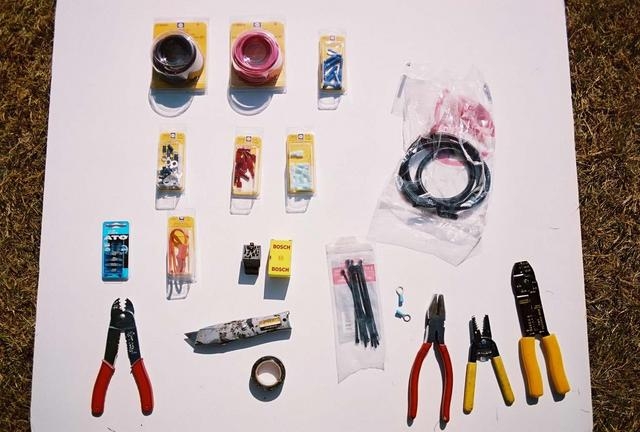
Parts List:
1 four pin 30 Amp relay, e.g. Bosch (relay holder and assorted pins optional)
8 ft of 14 or 12 gauge red wire (color is not critical but helpful)
8 ft of 14 or 12 gauge brown wire (for the new fuel pump ground)
8 ft of 18 or 22 gauge green wire (to extend the trigger signal switched wire)
8 ft of 18 or 22 gauge brown wire (to extend the trigger signal ground)
2, 1/4" insulated (covered) female spade connectors for 18 to 22 gauge wire
2, 1/4" insulated (covered) female spade connectors for 14 to 12 gauge wire
2, round terminal connectors, 1/4" hole, for 14 to 12 gauge wire
2, butt connectors, step down (22/18 to 14/16 gauge) (or soldering iron, solder and heat shrink)
1, heavy duty fuse holder complete with two 6" pig tails (12 or 14 gauge)
1, 15 amp fuse for the fuse holder
6 feet of black corrugaged plastic wire loom (cover)
1 small plastic empty clean margarin tub c/w cover.
electricians tape
a sharp knife or box cutter
wire cutters and strippers
"W"-style connector crimpers.
A straightened coat hanger
Alternative 1: 2 butt connectors for 18 to 22 gauge wire
Alternative 2: 2, plastic "T" taps for 18 to 22 gauge wire
Here is a photo of the basic parts
The Procedure
NOTE: We take no responsibility whatsoever for any damage that may or may not result from following this procedure either while performing the procedure or after its completion. If you do not have the confidence or skills to perform this procedure successfully and safely, then either do not attempt it or have a professional mechanic complete it. Before you start, read this all the way through to familiarize yourself with what you are going to be doing. Also note that there are two alternatives to the trigger wire layout.
1. Remove the rear seat bottom by removing the two large black Philips (x head) screws (and washers) from the front of the seat bottom. Store these screws in the margarin tub.
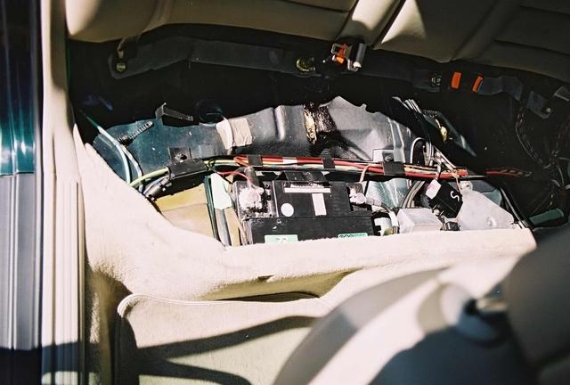
2. Inspect your battery. There should be plastic safety cover over the + terminal as shown in the photo.
If there is no cover, find one and install it before you complete finish this procedure. There should also be a clear plastic drain hose from the battery cap down to a rubber gromet in the floor. If this drain hose is missing then find one and install it before you complete the procedure.
3. Making sure that you have your car properly secured (in gear, emergency brake on, etc) AND you have the radio code, loosen the battery + terminal bolt and remove the + battery cable from the terminal. If the terminal is corroded, clean up the corrosion, e.g. with baking soda and a small amount of water and lots of cloths and/or paper towels (place the discarded cloths and/or towels in a plastic garbage bag, not in your car). Note: The corrosion that I had (oops!!)
4. Loose the seat back by removing the two large shiny Philips (x head) screws (one on each side about the middle of the two outer passenger positions). Store these screws with the other seat screws in the margarin tub.
5. Open the trunk. Remove all the clutter that may be there and place it in a safe place out of your immediate work area. (You don't want to trip on it). You should be looking at only grey carpet. Its like a clean desk. You probably only get to see it once and a while.
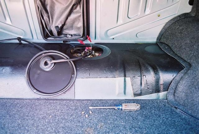
6. Remove the carpet piece on the "hump" by pulling back the floor carpet at the corners and removing the two black quarter-sized discs (one at each side) and then remove the two discs at either side of the hump. Place all four discs in the margarin tub. Note how the carpet hooks over the threaded pins and then pull the hump piece off the pins and out of the car. Place in a safe place. Back at the car, you should be able to see a round flat black cover on the hump just to the right of the ski sack. This is the fuel pump cover plate. See photo.
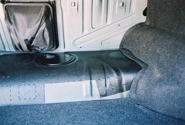
7. Remove the fuel pump cover plate by removing the three small chrome Philips screws. Place these screws in the margarin tub. Gently pull up on the cover. Note how the factory routed the wires (in the plastic cover sheath). See photo.
8. Release the fuel pump wires by leaning or crawling into the trunk and noting the location and position of the fuel pump wiring plug. Remove the plug by gently prying the brown hook tab on the right side of the wiring plug and then lifting the plug slightly to the left (this should release the left hand hook tab - if it doesn't you'll need to gently pry that tab slightly as well).
9. Pull the plate and plug up away from the fuel pump and into the trunk so you have better access to the wiring.
10. Near the plug, carefully slit the plastic sheathing (DO NOT TOUCH OR CUT ANY OF THE WIRES) and open it up about 6 inches so you can see all four wires: a yellow striped green (the fuel pump power), a larger brown (fuel pump ground), a thin purple (fuel gauge sender power) and a thin brown (fuel sender ground).
11. Now the first "scary" part, boys and girls (insert Count Floyd howl here). You are going to cut the yellow striped green wire and the thicker brown wire, about 2.5" back from the plug. Do it, do it now. DO NOT CUT THE THIN PURPLE OR BROWN WIRES!!
12. At the long end of each of the cut wires, separately wrap the ends in a small clean piece of electricians tape (NOTE: This is for Alternate 2, for Alternate 1 you will be pulling these wires back).
13. At the short ends, strip the wire cover (being very careful not to cut ANY of the copper wire strands) sufficiently long for either the butt connector you are using or the twist, solder and heat wrap technique you will be using in a few minutes.
14. Approximately 2 inches outside of the rubber grommet carefully cut a small hole in the plastic sheath - DO NOT CUT ANY WIRES INSIDE. GO SLOW AND BE CAREFUL.
15. For Alternate 1, pull the yellow striped green wire and the thicker brown wire back through this hole in the sheath. Now, through the hole feed your new 14 or power cables through the sheath, towards the fuel pump plug.
16. Strip the appropriate length of wire cover from the ends of these power cables to make the appropriate butt connector or soldered joint.
17. Make the connections to the short plug wires. The red wire should be connected to the yellow striped green wire and the brown wire should be connected to the brown wire. NOTE: IF you are soldering, practise on some scrap wires until you can get a nice "Chrome" joint. ALSO, if you are soldering, remember to put your heat shrink tubing over the large wires and well way from the joint BEFORE you join the wires and start soldering. "D.oh!" is not part of this procedure.
18. If you are a happy with the connections, tuck all the wires in the split plastic sheath and tape the sheath with electricians tape.
19. If you are doing Alternative 1 for the trigger wires (the ones you pulled back out of the plastic sheath, strip the ends sufficiently for the 22-18 gauge butt connectors, strip the ends of your trigger wire extensions (18 gauge wire in green and brown) and connect green to green/yellow and brown to brown.
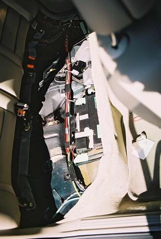
About this time, your trunk may look like this:

19. Place the long ends of the new power cables (and the trigger wire extensions in Alternative 1) in the black corrugated plastic wire loom, starting at the hole in the OEM plastic sheath. When you are done, tape the end of the new plastic wire loom to the OEM sheath (at the hole) with electricians tape.
20. If you have some, place a drop of Stabilant 22A contact enhancer on each of the four female plug connectors and reinstall the plug to the fuel pump. (It only goes on one way - it should go on easily - if not check the internal orientation and try again). Tuck the wire sheath into the same position it was in before you removed it (likely a kind of curl around the pump).
21. Reinstall the fuel pump access plate using the three small chrome Philips screws in the margarin tub.
22. Gently bend the wires in the corrugated plastic cover and instead of heading to the left side of the trunk (like the OEM sheath does), head them to the right side of the trunk, along the bottom edge of the trunk bulkhead. Don't go too far yet.
23. Now go into the back seat area, passenger side and gently pull the bottom corner of the seat back away from the trunk bulk head. Prop it away using something non-scratching (I used the wiring package).
24.Back in the trunk, tape the long end of the power cables (and trigger wire extensions in Alternative 1) and the plastic sheath to the end of a straightened coat hanger. About six inches from the right hand side of the hump and trunk bulkhead, there is a gap at the lower edge of the bulkhead. Shove the taped end of the coat hanger through this gap. If you have a helper have them grab the end of the coat hanger when it comes through into the passenger compartment. Gentley pull the wires into the back seat area.
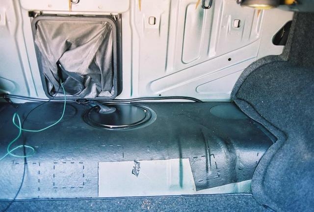
25. Remove the tape from the wires and corrugated cover and gently route the wires along the bottom of the trunk bulkhead and through the gap on the trunk side and in the slight depression in the body on the passenger compartment side. Make sure you have enough wire to get to about 6 inches to the centre from the battery. In the trunk, your wire routing should look like this:
26. Replace the hump cover carpet (and bulkhead carpet if you removed it too) getting the appropriate bits over the threaded pins and adding the four plastic disc/hold downs from the margarin tub.
27. If you followed Alternative 1, skip down to Step 29, otherwise, you still need to extend the trigger wires to the relay. Start by going to the drivers side rear door area of the back seat. Find the yellow-striped green fuel pump power wire in one of the taped bundles and the brown fuel pump ground in another (smaller bundle). Note the location of these wires in relationship to the plastic wire tray that runs wires towards the battery.
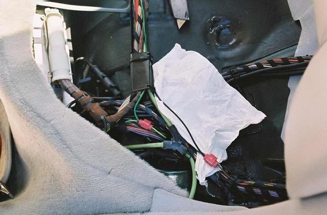
28. With the appropriate color and gauge wires located, open up the two wire bundles and "T" tap the yellow-striped green fuel pump power and brown fuel pump ground and run the new "trigger" wire extensions (green and brown 18 gauge wires) over to the battery area in the plastic wire tray (Note: The covers on the tray open up so open them and lay the wires in the tray and then close the covers again). The rougn positions of the t-taps are as shown in the photo below:
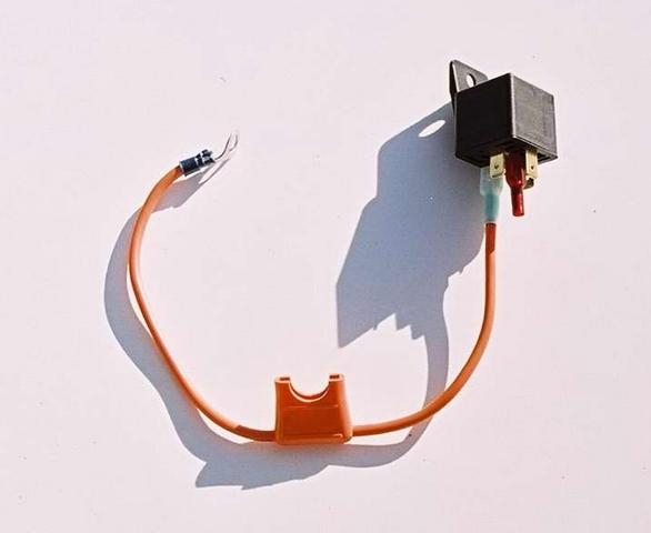
29. Now you are almost there. Just the final connections and clean up: Play with a position for the final location of the relay. Here is photo of the relay I used (actually a new 30 amp double pin 87/87 headlight relay that I had - just put an insulated male spade connector on the extra 87 pin). Note: I used a heavy duty spade-type fuse holder. Any good heavy duty fuse holder will do. DO NOT ELIMINATE THE FUSE HOLDER - your life (and others) may depend on it in an accident.
I chose the about the middle of the battery, attached to the bottom side of the plastic cable tray with a tie-wrap (BUT NOT YET!!).
30. Make the connections from the trigger wires (either from Alternative 1 or Alternative 2) to the relay using the insulated 22 to 18 gauge 1/4" female spade connectors. Make sure you have the 18 gauge trigger wires and not the 14 gauge power cables. As you do this, trim the length of the wires, if they are too long for the position of the relay. The completed insulated female connectors should be attached to the male connectors on the low voltage side of the relay. On mine, this was spades 85 and 86.
31. With the new fuse holder empty (no fuse installed), connect the fuse holder to the + battery and terminal 30 on the relay using a ring connector on the battery end and an insulated 12 to 14 gauge 1/4" female spade connector at the relay end. Without putting a fuse in the fuse holder, put the ring connector under the battery cable bolt nut (take the nut right off, slip on the ring connector and then put the nut on) and attach the battery cable to the + battery post again (don't break the post by over torquing the nut). Attach the other end with the insulated spade connector to pin 30 of the relay.
32. Find a nice comfortable groove for the new power cables in the corrugated plastic sheath and then pull the corner of the seat back away from the bulkhead. Remove whatever you had proping the seat back away from the bulkhead.
33. Test the lengths of the new red fuel pump power cable to the position of the relay and the brown 14 gauge fuel pump ground cable directly to the negative terminal of the battery. Trim wire length, as appropriate. Leave a bit extra but not too much - the longer the wire, the more the voltage drop.
34. Make a 14 gauge insulated female spade connection on the end of the red power wire and connect to the power out terminal of the relay (87 on the relay I used).
35. Make a 14 gauge ring connection to the end of the 14 gauge brown ground wire and attach to the negative terminal of the battery (remove the nut from the bolt, slip the new fuel pump ground over the bolt, add the nut and tighten (being careful not to overtighten).
36. Add a 15 amp fuse to fuse connector. Temporarily tape the relay to the side of the plastic cable tray. With everything completed except the tie wrap on the relay (or relay holder if you used one), your installation should look like this:

37. Start the engine. If it doesn't start, you have a problem with one or more of your connections. Check and tighten connections. When the car starts and you are happy, stop the car and permanently mount the relay to the underside of the cable tray (I used a nylon tie wrap).
38. Make sure that the corrugated covered cables avoid touching the battery drain tube. Reinstall the two shiny Philips seat back screws. Reinstall the seat bottom with the large black Philips screws.
39. Enjoy.
The end result was the fuel pump sees about 0.27 volts less than the battery at idle (before it was 1.0 V). Under load (WOT) where before I got 11.82 V, I now get 12.98 V. Has to help. In our case, the pinging problem seems to have (mostly) gone away. We can't guarantee that your results will be the same (hey, they could be better!!)
Dave F.


 -
-  -
-