UrS4 Seat Heater Controller Bulb Replacement with LEDs
The seat heater controllers on the UrS4 are illuminated by red bulbs
mounted in a molded clear plastic light pipe. Since these controllers
are lit whenever the ignition is on, the bulbs eventually burn out.
Although Audi's fix is to happily sell you a replacement controller
for mucho $$$, the bulbs can be replaced. I replaced them with LEDs
to (hopefully) avoid having to do this job again.
1. Remove the seat heat controller from the switch panel in the dash
(see Photo 1).

Carefully pry out the blanks at each end of the switch panel -
they are held in place with spring clips. This reveals the bolts
securing the panel to the dash. Remove the bolts (the upper bolt
on each side). Carefully pry out the 3 switch blanks in the panel.
Pull the switch panel out of the dash. There is not a lot of slack
in the wiring harness behind the panel. My panel hung up a bit on
the dash vent assembly and I had to ease it out. I pulled the left
side out first until the connector block released from the heater
controller. I then slid the panel to the left and released the
right side. The controllers are secured in the switch panel bays
with spring clips. They push out towards the rear of the car, but
it takes a bit of force. The first one I removed shot over my
shoulder and landed in the back seat, so be careful - don't catch
it with your face. Photo 1 shows the connector blocks that fasten
to the back of the controllers. These are loose, so you have to
hold them to re-install the controllers - but we'll get to that.
2. Disassemble the seat heater controller
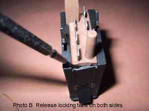
The black case has two locking tabs on the short sides that engage
the connector base (see Photo A). Insert a small prying tool (that's
what screwdrivers are for, aren't they?) into the opening at the
corner of the case and pry the locking tab away from the base (see
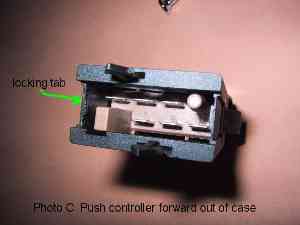
Photo B). Do this on both sides simultaneously and push the controller
guts forward out of the case (see Photo C). On reassembly, make sure
the locking tabs are engaged or the controller innards will pop out
when you plug into the connector

3. Don't plan on using a controller from a 200!
Even though the faceplates are the same, the UrS4 controller is
completely different than those from the 200. Photo 2 shows both
controllers side by side - the UrS4 controller is a larger and more
sophisticated device. Photo 3 shows the innards of both controllers.
The 200 controller uses a clear bulb in a red plastic light pipe. The
UrS4 controller uses a red bulb in a clear plastic light pipe.


4. Remove the old bulb.
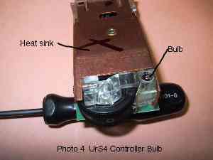
Photo 4 shows the bulb installed in the socket in the plastic light
pipe. This socket is partitioned in two at the bottom and each
partition tapers to the hole in the PC board to guide the bulb
wires through the hole. Photo 5 shows the bottom of the PC board
and the bulb wire solder joints. Note which is positive and negative
- this is critical when using LEDs since the LED will only work
connected one way (the right way, of course). The true enthusiast
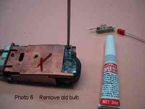
can remove the bulb by unsoldering the heat sink and disassembling
the controller, or you can do what I did - unsolder the bulb wires,
crazy glue a stick to the top of the bulb, and pull it out (see
Photo 6).

5. Choose the replacement illumination.
The OEM bulb is 4 mm in diameter and 11 mm long. Total length with
leads is 20 mm. It's more difficult to find small red 12v bulbs
than clear bulbs. LEDs have no filament and typically have a longer
life than a bulb. The downside is LEDs broadcast most of the light
out the top and little to the sides, so the design of the light pipe
is not optimal for LEDs. Most LEDs also require a resistor to
decrease the voltage from 12v to the operating voltage of the
LED (usually around 2 -4v). I picked up a couple red grain of
wheat bulbs from a local hobby shop, but they looked pretty
tacky and the salesman said life was variable. Photo 7 shows
the OEM bulb and the LEDs I chose to try. The large red LED is a
12v unit with an integrated resistor from Radio Shack. At 1.5 mcd
it's lumen output was pitifully weak and it was too large, so I
ruled it out. The other LEDs are from the ashtray illumination in
an A4, courtesy of one of the local Audi techs. These are high
output units and throw a lot of red light. They look like a T-1
size high brightness LED - about 3 mm diameter and 5 mm long.

Addendum: Since I first published this how-to, Joe Petersack
found a T1 size bright red 12V LED that fit these controllers.
It is a Linrose Super Brite LED #B4302F1-Red. Joe says these
throw the right amount of light. I've also received T1 size 12
volt LEDs from SUNLED Corp (#LMR32D-12V) which look like they'll
do the job. This eliminates the voltage dropping resistor.
6. Install the LEDs
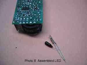
I soldered the resistor to the anode of the LED. The assembly has
to be short enough to fit inside the existing socket in the light
pipe. Photo 8 shows the assembled LED and the original bulb. The
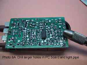
holes in the bottom of the bulb socket are too small to pass a
resistor lead, so they have to be drilled larger (see Photo 8A).
Make sure the anode of the LED connects to the positive terminal
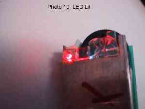
on the PC board. Photo 9 shows the LED installed and Photo 10 shows
it lit.

7. Re-assemble the controller.
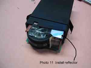
LEDs broadcast most light out the top of the LED and little to the
sides, unlike a bulb. I made reflectors out of aluminum pie plate
material and installed them over the top of the LEDs to reflect
light back into the light pipe (see Photo 11).
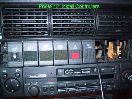
8. Re-install the controllers into the switch panel.
I found this easier in reverse order of removal. I slid the left
controller partway into the panel bay, held the connector block,
and slid the controller into the block. Push the controller home
into the bay and install the switch panel left side first (see
Photo 12). The right side connector block can be held through the
3, uh, make that 2 empty switch bays beside it while the controller
is pushed into place. By gosh, where did that Antilock switch come
from? Install the panel bolts and clip the blanks into place.
9. Enjoy!
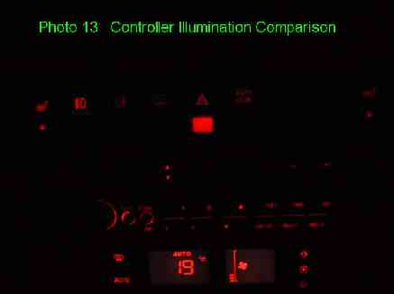
Photo 13 shows a night shot of the switches illuminated. The LED
illumination in the controllers nicely matches that in the other
switches.
Wow, everything on the car is working again!
That's it!
Fred Munro
'94 S4
|