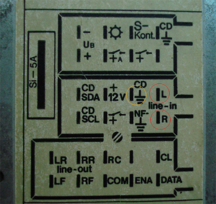
First, pull your radio out and locate the 3 harness plugs on the back. Again, the following diagram is for the Gamma radio. If you have a newer radio, refer to the diagram stuck on the top, the pin locations may have changed. The 3 wires we will tap into are circled below. Red circles indicate the line-in leads from the CD changer, the yellow circle is the ground.
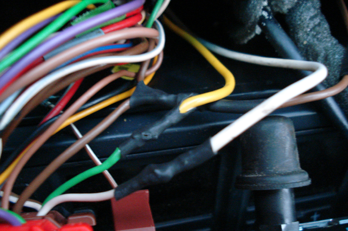
Next, cut the three wires with enough slack so that you can solder new wires onto them. Attach/solder a sufficient length of wire to each of the 4 line-in wires and run all 4 to your DPDT switch, making sure to keep track of which two go into the radio, and which two come from the changer. Also attach/solder your ground wire, while leaving the original connection in tact, as shown below. Run the ground wire to your input jack, it will not attach to the switch. I chose to use heat-shrink tubing on my connections but it is not necessary.
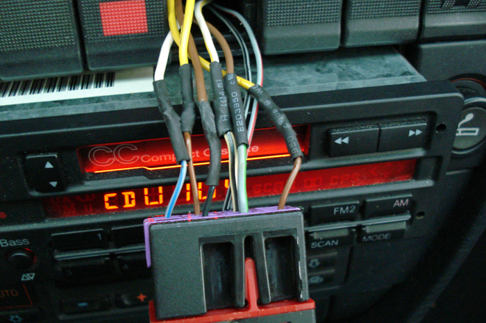
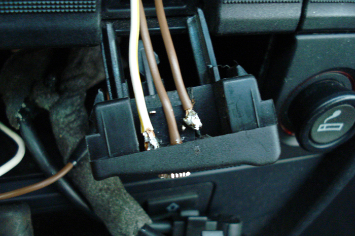
Now you need to connect the wires to your DPDT
switch, pictured below is the wiring at the back of mine. I used a "FUNK" switch
found in European C4s for CB radio, which is not a DPDT switch by nature but I
modified it to act as so. Any DPDT switch will work, there are many variations,
and the wiring locations will be different for each. You can find them at your
local hardware store amongst other places. As you can see, I had a lack of extra
wire so unfortunately nothing is color-coded. The 6 wires wrapped in heat shrink
below are the ones of importance, the two wires you see in the background are
power for the switch illumination.
Two of these 6 wires are your switch output to your radio's line-in, two are
your CD changer input, and the last two are your auxiliary input. This leaves a
total of 3 wires connecting to your aux input jack.
Here is the 1/8" stereo input jack I used, can be found at Radio Shack.
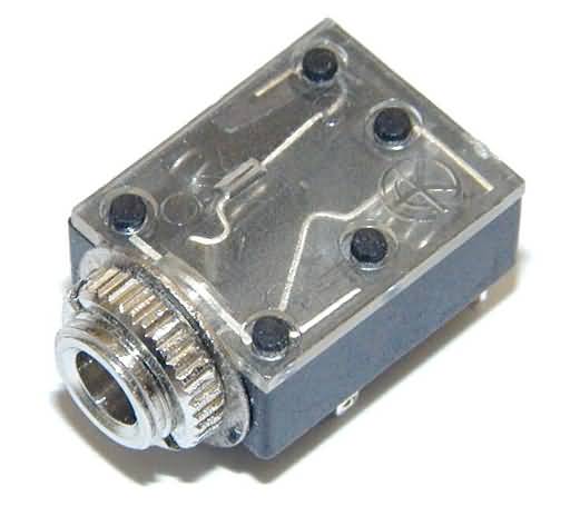
Input jack wiring diagram - Thanks to Jared ("Chapel") for the diagram:

Wires connected to the jack. Outermost are the Left/Right channels (Pins 2 & 5), center brown is the ground (Pin 1).
Finished product! The FUNK switch "out" leaves
the CD-changer connected, when it is depressed the aux jack becomes active.