
About oxygen sensors
Oxygen sensors are one of the most important emissions control devices on your car. They were introduced in production cars in 1976 (as the basis of the Saab/Bosch Lambda-Sond system), and have evolved remarkably little since then. But while their function has changed little over the last 30 years, their importance in engine operation has increased greatly - a recent study stated that 70% of fuel injected cars that fail emissions tests have bad oxygen sensors. A faulty oxygen sensor can cause several symptoms, including:- Failed emissions tests, typically due to high CO or HC
- Poor fuel mileage, typically due to rich fuel mix
- Fouled spark plugs, typically due to rich fuel mix
- Rough running and sluggish performance
- If let go long enough, damaged catalytic converters from rich fuel mix
- Lean mixtures improve fuel economy, but also cause an increase in nitrogen oxide (NOx) emissions. If the mixture is too lean, it may not ignite at all: this causes 'lean misfire,' which can cause rough idle, hard starting, stalling, extremely high hydrocarbon (HC) emissions, and even damage to the catalytic converter. Lean mixtures also increase the risk of spark knock (detonation).
- Rich mixtures are necessary when starting a cold engine, and additional fuel is also needed under heavy engine load. But a rich mixture causes high carbon monoxide (CO) emissions.
Though there are a few types of oxygen sensor out there, we will focus on the type that Audi used on the 12v engine.
Basic theory of operation
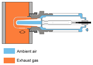 Oxygen sensors take advantage of the fact that fuel burns most efficiently when
the air/fuel ratio is 14.7 to 1. When there's a greater ratio of fuel to air,
the mixture is called rich; when there's a greater ratio of air to fuel, the
mixture is called lean. The oxygen sensor monitors this ratio using the Nernst
Effect. Nernst's law describes how to measure the electric potential difference
(voltage) between two materials in close contact if one is a known constant.
In the oxygen sensor, the two materials are a zirconium dioxide sensor, and the surrounding air. The ceramic zirconium dioxide sensor is a hollow cone-shaped element coated inside and out with a thin layer of micro-porous platinum. The sensor 'thimble' is encased in a protective steel tube which extends into the exhaust manifold. Reference outside air comes through a hole in the back of the sensor body and interacts with the hollow inside of the thimble. When the ceramic sensor is in the temperature range of about 325°C to 350°C, it accurately registers the difference between the oxygen content of outside air (the constant) and exhaust gas oxygen content as a voltage signal which is proportional to the difference between exhaust gas oxygen content and that of outside air.
How? I'm glad you asked.
The construction of the sensor is, in effect, a galvanic cell, like a flashlight battery. At the proper operating temperature, the ZrO2 thimble becomes electrically conductive, and attracts negatively charged oxygen ions, which collect on the platinum surfaces on both surfaces (inner and outer) of the thimble. Since there is more oxygen in regular air than in the exhaust stream, the inner surface of the thimble will collect more ions than the outer surface. This will cause an electrical potential difference - voltage - which can be measured by the ECU. The concentration of oxygen in the exhaust stream determines the number of ions on the outer surface, hence the amount of voltage produced. If the engine is running rich, there will be relatively little oxygen present in the exhaust gasses, so fewer ions will be available to attach to the outer surface, and the voltage output will be relatively high. Conversely, if the engine is running lean, there will be more oxygen present to bind to the outer surface, so there will be a smaller electric potential, thus lower voltage.
Single-wire sensors rely on exhaust gasses to heat the element to operating temperature. It takes several minutes after the engine is started to reach the operating temperature, and if the car sits at idle for too long it can cool down below the threshold of operating temperature. The ECU knows that it will not get an accurate signal from a cold sensor, so it will operate in open loop mode, holding the mixture at a fixed setting. Since emissions are lowest when the ECU is operating in closed loop mode, it is desireable to get the oxygen sensor to its operating temperature as soon as possible after the car is started, and keep it there. Hence the three-wire sensor, in which two wires power a heater that brings the sensor to operating temperature in 30-60 seconds, and maintains that temperature even at idle. Since condensation on the inside of the sensor can cause damage under certain circumstances, the post-cat oxygen sensors are not heated until the catalyst reaches a precalculated temperature.
The ECU can't keep the air/fuel ratio constant all the time, so instead it is constantly oscillating between slightly lean and slightly rich. As the sensor voltage swings from high (about 1.3V) to low (around 500mV), the ECU corrects the mixture: under about 450mV, the ECU registers a lean condition; past around 900mV, a rich mixture is registered. The oscillation is called 'cross-counting' and its frequency and amplitude are important.
Age and contamination will cause the oxygen sensor to fail. Age can't be helped; contamination can come from several sources:
- Certain fuel additives
- Lead
- Silicone (i.e. from antifreeze leaking into a cylinder)
- Phosphorus (i.e. from oil burning)
- Oil, cleaners, water, or other chemicals spilled on the sensor
A (not so) quick aside
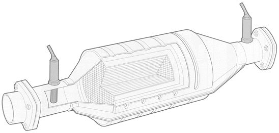 Modern (OBD-II compliant) ECUs have two pairs of oxygen sensors: one is the pair
that older cars have, before the catalytic converters; the second pair is after the
catalytic converter, and monitors catalytic converter function. So before we get
to the ECU's handling of oxygen sensor inputs, let's take a quick look at the
catalytic converters.
When congress passed the Clean Air Act of 1970 which required a 90% reduction in auto exhaust emissions, it generated a lot of controversy, especially among automakers, who didn't think that such a reduction was cost-effective (or even technically possible). This tune changed somewhat when Ed Cole, General Motors' president at the time, told the Society of Automotive Engineers in January 1970 that the 'pollution free car' mandated by congress could only be achieved if lead was taken out of gasoline, and cars used this newfangled device called a catalytic converter. Taking the lead out of gasoline was vital not because lead was an environmentally harmful pollutant (in 1976, in response to a lawsuit, the EPA ruled that while lead was not a certain health risk, 'awaiting certainty will allow for only reactive not preventive regulation.' I guess it turns out that it was the right thing to do), but the lead would deactivate the main catalytic element, platinum. |
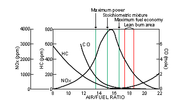
 So meeting the (at that point) strict HC/CO emissions standards was achieved by
the introduction of oxidizing catalytic converters. Oxidizing catalytic
converters have to reach an operating temperature of 250°C - 300°C before
oxidation of CO and HC occurs. The amount of time required to reach operating
temperature varies by catalyst design and position, but could take anywhere from
20 seconds to two minutes. The use of these catalytic converters through the mid
1980s, as well as the introduction of other emissions control devices (EGR systems,
computer control, faster converter light-off, etc) achieved great gains, but
the 1981 emissions standard which stipulated no more than 1 gram/mile NOx emissions
could not be achieved by current technology. So two different catalytic
approaches gained widespread application to meet the requirements: the three way
catalyst, and the dual catalyst. Three way catalysts are capable, within a
narrow range (+/- 0.05 from optimum) of exhaust stoichiometry, of simultaneously
decreasing NOx, HC, and CO with reasonably high efficiency. Oxygen sensors are
required to maintain the narrow range of exhaust stoichiometry.
|
 Those who took chemistry in high school will undoubtedly recall that a catalyst
is a material that promotes or accelerates a chemical reaction; sometimes a
catalyst is even required for the reaction to take place. The catalytic converter,
as its name implies, provides a catalyst to make certain chemical reactions in the
exhaust stream happen.
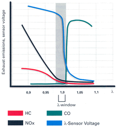
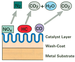
The catalytic converters have three important layers. First is a wash coat, which increases the surface area that the catalysts are on: a large surface area is essential for high-efficiency exhaust emission reductions. Next, a layer of noble metals like platinum and palladium are vaporized on to the wash coat; these encourage carbon monoxide and hydrocarbons to react into water vapor and carbon dioxide. Then there is a third layer of platinum and rhodium that reduces nitrogen oxides (the third layer is what makes the converter 'three-way'). These reactions seem contradictory: the oxidation process is more efficient when large amounts of oxygen are present, but reduction happens more efficiently in a low oxygen environment. But there is a small window of exhaust stiochiometry, called the lambda window, which creates favorable conditions for both reactions to take place. Maintaining the air/fuel ratio to keep exhaust gasses in this window is extremely important, hence the requirement of oxygen sensor monitoring. |
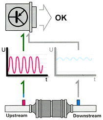
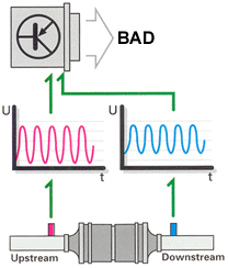 A catalytic converter that has been damaged by aging or other defects will
suffer from a lower oxygen storage capacity, which means that its catalytic
effectiveness is reduced. If the applicable limits for exhaust gas hydrocarbons
are exceeded by a factor of 1.5 in official emissions testing, the condition must
be recognized by the ECU. To this end, OBD-II cars have a second set of oxygen
sensors that sit after the catalytic converters. The ECU then monitors catalytic
converter function by comparing the respective voltages of the sensors installed
before and after the converters. The result of this comparison is an amplitude
ratio between the two sensors. If the ratio is out of line, a trouble code is
stored and the Malfunction Indicator Light is turned on.
|
How the ECU uses oxygen sensor data
OK, back to the sensors.
 As mentioned earlier, the oxygen sensors monitor the amount of residual oxygen
remaining in the exhaust gas mixture. The ECU responds to changes in the
composition of the exhaust gas by varying its control of various functions. The
sensor readings and corresponding control changes form part of a closed-loop
circuit designed to consistently maintain an optimum air/fuel ratio. This is the
'loop' that people are referring to when they describe engine operation as being
'open loop' or 'closed loop': if the ECU for some reason (say Wide Open Throttle
conditions) decides that it's OK to look the other way and let emissions control
slide for a few seconds, it breaks the circuit (goes 'open loop'), generally to let
the air/fuel mix be a bit rich, for a short a power boost.
The oxygen sensors downstream of the catalytic converters do not have any part in this process; they only monitor the function of the catalysts. If the upstream oxygen sensor is malfunctioning or damaged, it will be impossible to maintain the optimum air/fuel ratio required for proper catalytic converter operation. Because of this, the ECU constantly monitors the output of the sensors making sure that nothing is awry. |
Closed-loop diagnosis
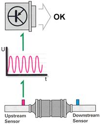
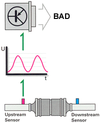 But it's not that simple. Aging and contamination affect the oxygen sensors'
response characteristics. Reduced sensor effectiveness may be reflected in
extended reaction times (lower frequency) or a displacement of the sensor's
voltage curve (phase shift). Either of these conditions will cause the engine
to operate outside of the lambda window, which would create a negative effect
on emissions and catalytic converter life. To get around this, the ECU monitors
oxygen sensor response characteristics and peak voltage output.
If the ECU decides that the pre-cat oxygen sensor readings are not correct, or if the signal is lost (due to short- or open-circuit), the system responds by cancelling oxygen sensor control and supressing the adaptation function. Then to maintain reasonable operation of the engine, the EVAP control system reverts to a backup operation mode (to control the amount of gas vapor entering the air intake through the EVAP frequency valve) and the ECU operates the fuel map according to a stored backup program. There is no backup operation mode for the post-cat oxygen sensors, since they do not affect operation of the engine. |
Sensor replacement
Nobody wants to buy the sensor actually listed for the 12v, because they cost well over $100 and you need at least two of them (sometimes four). Since all Bosch heated thimble type sensors are the same, just with different harnesses, one solution is to get the Bosch sensor for another car that doesn't command the same level of markup (my favorite is the #13913 sensor, used on various Fords but Bosch has come up with a 'generic' one that you can use as well) and splice it in to the Audi harness plugs. There's no problem with this, as long as you make a good electrical and mechanical connection on the wires, seal them properly against contaminants from the engine bay (wrapping the splices with electrical tape will not accomplish this), and use the right type of sensor. The replacement sensor needs to have the same heater wattage and performance characteristics. Since all Bosch 3-wire heated thimble type oxygen sensors are the same internally, any Bosch 3-wire heated thimble oxygen sensor is a fine replacement. 1-wire sensors and 4-wire sensors are not like the 3-wire sensors, and different brands will have different characteristics, so don't press your luck. In particular, the electrode power grid on Bosch sensors contains more platinum than other brands, which affects the signal output.In theory, a 4-wire sensor is the same internally as a 3-wire sensor, and the fourth wire is just a ground. In those cases, you can just ground the fourth wire and otherwise the sensor is identical. However, there are some newer 4-wire sensors with very different characteristics so be careful. If your 4-wire sensor is a heated thimble type, you should be OK.
|
|