XTB Boring/Tapering Process
Courtesy of: Mance Etheredge

 
Step-by-step TB boring/tapering process from ultrasonic cleaning thru XTB...


Rather than show a bunch of pics after the work is done I'm going to walk everyone thru the machining process.

This pic is of a stock TB thats been ultrasonically cleaned before any machine work begins.

I'll limit pic content to just primary venturi until work progresses beyond it.

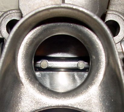
Pic 2: Perfect example of bore inlet mis-alignment on stock throttle body...


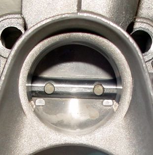
In this pic you can clearly see that the bore inlet is not aligned with the butterfly plate. If you look closely the new over-size bore appears to be slightly off-set to the left (less inlet rim material remaining at the 9:30 position than at the 2:30 position). That is no optical illusion. While the caster of these throttle bodies is very good at centering the hole within the stepped inlet they are VERY bad at centering that hole perfectly aligned over the butterfly plate or bore. I've seen them as bad as .035" offset with most hovering nearer .020". The one in this pic is off-set .0255" from perfect center. And you can't use the butterfly shaft screws as any measurement of center either as they are a "one-size-fits-all" assenbly as well as are the shafts which are slotted longer to move the plate around in and the holes thru the plates are larger than cecessary to allow centering. You MUST bore to the centerline of the butterfly plate's surrounding "precision honed" bore or everything is out of whack. This can ONLY be done aftera throttle body is assembled. Thats why Audi doesn't do it. They make loose tolerances then assemble the plates into an already cast throttle body. And you can't do this "zero tolerance" aligning with a hand-held die grinder.

Those DIY'ers that are going for uniform bores here based on this step are killing themselves efficiency-wise as they are creating more air-flow while orienting the air column offset, or even worse, diagonally to one side or another without regard for true center. This causes turbulence when all air is deflected to one side of the butterfly while the other side of the butterfly is moving less or no air.

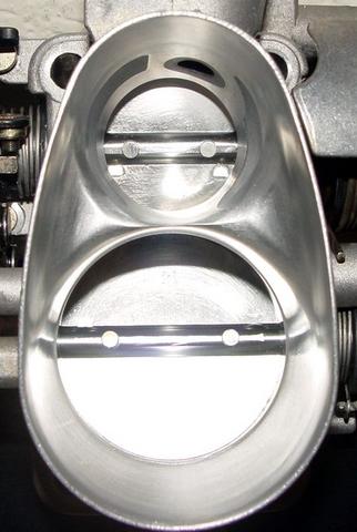
In order to flow effectively the bore inlet must be perfectly oriented and aligned with the butterfly opening and not with the inlet opening in the top of the primary venturi.

Pic 3: End of machined process for S1 TB...


The TB in this pic is destined for XTB status when complete so ignore the filled hole for purge provision on S1/S2. Only XTB will have this hole filled due to depth of taper. While this little angle-cut looks like such a small process the results from it are gape-jawed STAGGERING!!

Note the I.D. bore has already blown thru the exterior walls on both sides of the purge valve port. The dark gray patches are epoxy putty put on after ultrasonic cleaning and drying then cured at 250 degrees for 12 hours before machining.

All that's been done here is a proper degree of taper just at the TB inlet. This with the new bore diameter is THE most important machined aspect of this TB. The S1 from this point will be finished by hand grinding/honing. This concludes all machine work done on the S1.

Pic 4: End of machined process for S2 TB...


Here's the Stage 2 bored and tapered. Still need to drill the provision for the purge valve but I'll get to that after I now go back and finish the machining that will take this to XTB specs.

Back in a few with the last pic in this series.

Pic 5: End of machined process for XTB...


Throttle is now machined to XTB spec and purge valve port has been drilled then reamed to spec. Taper runs all the way from flange gasket inlet edge to bottom of primary bore floor. Same degree of taper uniformly all the way around the bore, top-to-bottom-left-to-right-front-to-rear. It's now one big velocity stack with what my flow testing has shown to be the ideal/optimal degree of taper. 1/8 of a degree more/less taper causes a loss in velocity as well as volume. This degree is what I wanted all along in the S3 TB's but could never quite get due to sleeve thickness or smaller outlet bore. It's now EXACTLY the angle and outlet opening I've always wanted. Don't even ask what those are cuz I aint tellin!!

Next the Rotofera does it's magic on shaping & contouring the bow-tie and bevelled edge around the flange I.D. and then I move to the Foredom for some finish-up and finessing the appropriate cross-hatching/swirl polishing. Then a final ultrasonic cleaning to clear any metal grindings/slurry, re-lube the bearings and box em up for shipping.

There ya have it... start to finish on whats involved in machining S1-XTB throttle bodies.

This is the finished 707CFM XTB...


not that there's any way to tell from this pic but this is the "hard-to-find" and rare throttle body. This shows an XTB finished with the best finish-hone for flow. The Rotofera makes all this hand-shaping and contouring a cake-walk but I also use the Foredom for about a third of this work and the new Lithium Ion cordless Dremel for getting into some of the tighter places.

In case some of you havent heard of the new cordless Dremel it's an incredibly good tool for sub-$70 at Lowes/Home Depot and comes with 65 or so accessories... well worth having around. Definately NOT for the IM Workshop but works for about everything else. Same torque and RPM's as the "plug-in" unit. All Dremel cordless units that preceed the LI are junk, totally worthless in comparison. This one is the REAL DEAL! 'Bout friggin time too.