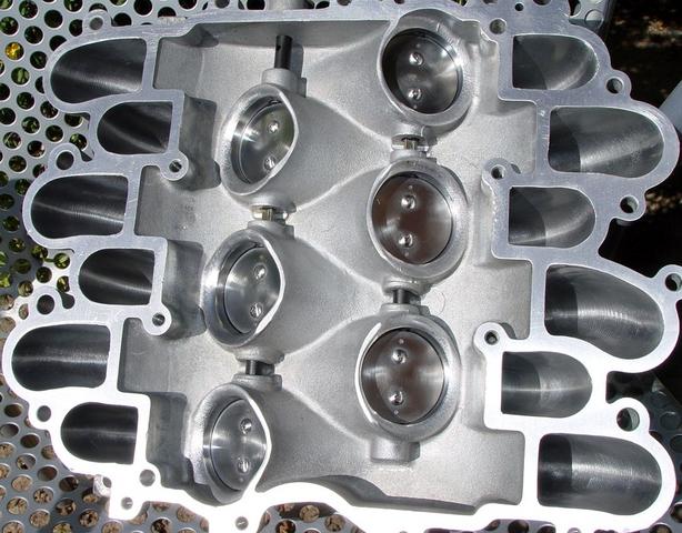
Those that have been following along should be close to having an intake manifold top that closely parallels this one's state-of-finish. The top half will now be taped off with 2" masking tape to prevent dirt, dust and other contamination from getting inside. It will stay that way until I'm ready to bolt it back to the lower manifold.
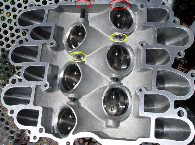
There's some special areas of concern during re-assembly that I've circled in red/yellow so they aren't overlooked.
The red area refers to the butterfly shaft o-rings that are hidden within the aluminum bushings that linkage assembly protrudes from and that the actuator valve rotates during manifold switch-over. They are "directional" o-rings and MUST be installed the same way they were removed. Install them backwards and you'll be chasing a small vacuum leak and subsequent erratic idle and off-idle hesitation problem forever. They can only do their job and prevent a vacuum leak if installed with the sealing lip that exists on one side of the o-ring facing outwards (away from the intake manifold. Internal vacuum then pulls (sucks) this lip flat against the switchover rods bearing material and seals it.
The second area of note is marked by the yellow circles in the above pic. We all pulled little plastic spacers out of there upon disassembly that were so fragile and heat-fatigued that most cracked and crumbled upon removal. While those spacers, in and of themselves, are expendable/unnecessary the job they accomplish on re-assembly is imperative, They align the butterfly shafts to the bores. An easy work-around is to push a pair of needle nose pliers between the machined flat on both bore O.D.'s. The idea is to center the slight protrusion of bearing material so that you can then re-install the butterfly plates and have them centered within their bores and the same amount of axial (in/out) play of the butterfly shafts. If this method is not used one shaft can have more axial play than the other and cause a "binding" of the linkage when pushed/pulled by the actuator vacuum diaphram ball-socket.
First pic shows butterflies open so you can see degree and depth of finish underneath them.