Hi-flow Airbox Workshop Part 3: Airbox
lid, o-ring sealing, hi-flow VS outlet, and RS3 MAF mods...
I've spent the last 2 days in their entirety working on the airbox lid. Trying to improve what's been done over the years and create an o-ring sealing feature that eliminates the gasket altogether and features an o-ring instead. This o-ring has now been tested to 125psi peak & hold test. No leakdown at all in 6 hours. It was also tested under a vacuum at 24InHg and also held that for 6 hours without a loss. Important to note only Hi-flow Velocity S and MAF were tested at these pressures and NOT the assembled airbox. Tho this does mean there is no leakage between airbox lid and HFVS underneath or between airbox lid and MAF flange up top. I would've imploded/exploded the plastic airbox at either of those extremes had I pressure tested it. In contrast the stock cork gasket doesn't even begin to accomplish an air-tight seal. It will leak down at even 1psi or 60 psi within second or two. Same with similar vacuum levels. It's "just" good enough to keep "unmetered" air out of the system and nothing more. None of this is very meaningful in our situation but "if w're gonna be a dog, why be a Chihuahua!?!"
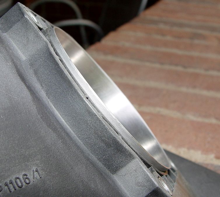
First pic shows a machined HFVS outlet protrusion from the airbox lid after being swaged into the airbox outlet under pressure to form a tapered outlet and thus compressing it solidly into the plastic airbox outlet orifice. I mean this sucker is in SO tight it would be harder to get off than Martha Stewart on dirty sheets!! I ruined 3 just getting to this point. Every one has to have it's outlet edge folded inward with channel locks to get it out.
All airbox pics from here on will appear a little more "grayish" as both top, bottom, inside & out of airbox has been bead-blasted for better adhesion of the planned commercially applied bed-liner
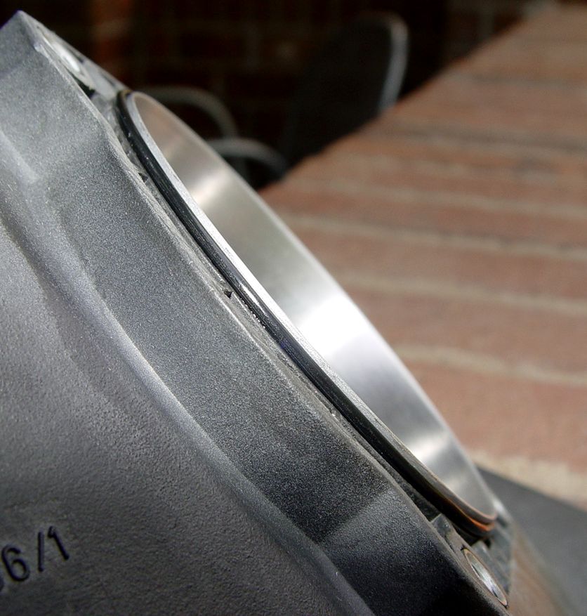
Pic 2; 3" ID X .0625" cross section o-ring used for sealing HFVS/RS3MAF to airbox lid...
Pic 3: RS3 MAF modifications required to accomplish the o-ring sealing provision...
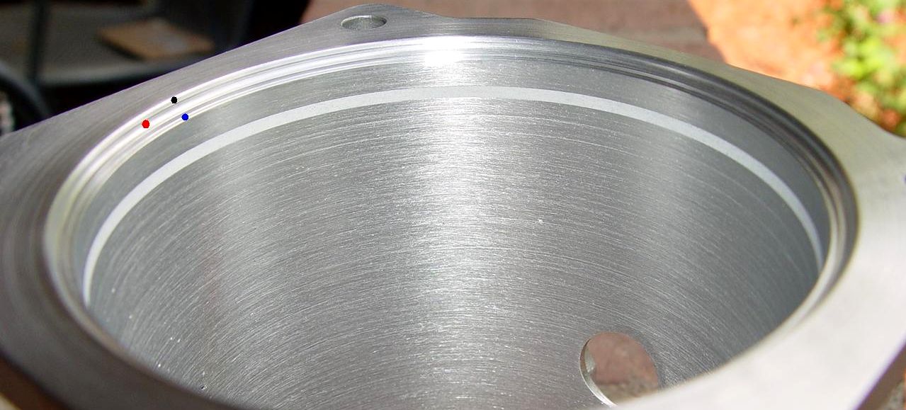
I've placed small colored dots at the 10 o:clock position in this pic to help understand what's been done.
It was important to me that this be as "hi-flow" as possible with no gaps, raised edges or even feelable differences between the MAF housing and the HFVS.
Black Dot: Is the o-ring lead-in taper. It is what permits the MAF to be screwed down to the airbox flange and compress the o-ring into it's sealing seat.
Red Dot: Is a radiused sealing seat that locks firmly down on to the o-ring when MAF is tightened to airbox lid.
Blue Dot: Is the precision-fit flat machined into the MAF inlet that forces the HFVS OD to center within the MAF and since MAF groove is .0015" shallower than HFVS protrusion out of the aibox the MAF is always pushing down on the HFVS outlet edge. This MAF groove ID is also a tight interference fit to the HFVS outside diameter which locks it pefectly centered within the MAF ID. Neithe can move or ever go off-axis from each other when MAF is installed on airbox.
Gray epoxy putty has been filled into the old MAF screen retaining groove and honed to the same finish as MAF and HFVS.
Pic 4; Airbox with modified RS3MAF and HFVS installed...
This pic shows the mating edges all locked together.
In spite of what this looks like there is virtually no gaps or feelable height differences between the 2 aluminum parts. The camera and/or flash does funny things with pics like this.
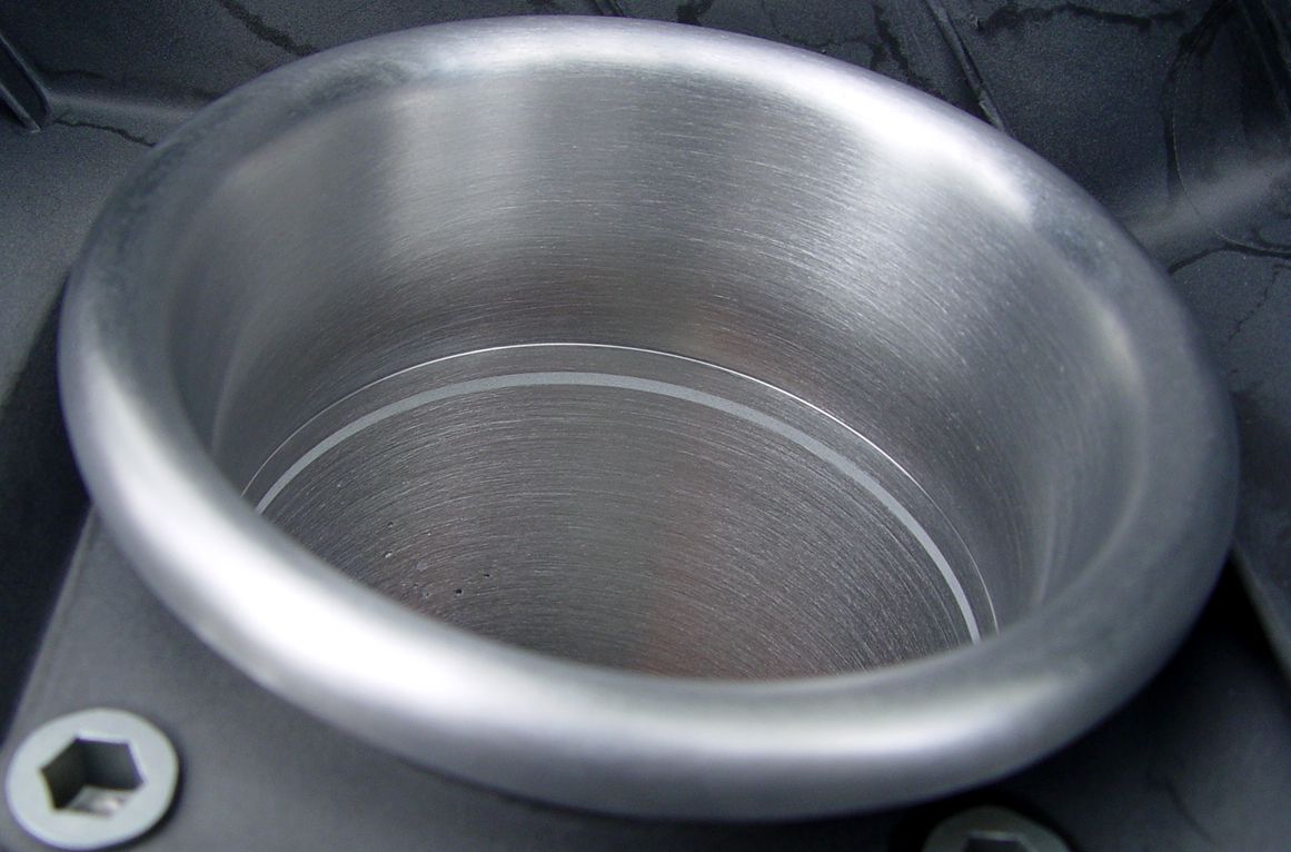
Pic 5; HFVS/MAF "thru-the-bore" inside looking out picture...
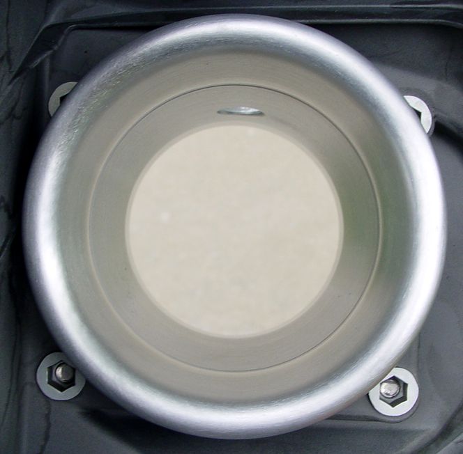
This time with no flash but now the epoxy-filled screen groove appears to be a "raised" edge but it is absolutely NOT raised.
Pic 6: MAF/HFVS "thru-the-bore" outside looking in picture...
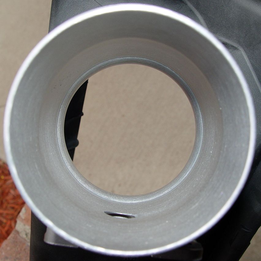
This concludes the "Hi-Flow" airbox lid aspect of the workshop. I'll come back to the lid once finish is chosen but this is about all I can do "flow-wise" given my needs today or in the forseeable future.