Part 1: Hi-flow Airbox Workshop...
I've gotten as far on the B4 high-pressure air compartment as I can get without having the mating Hi-Flow airbox it will integrate with.
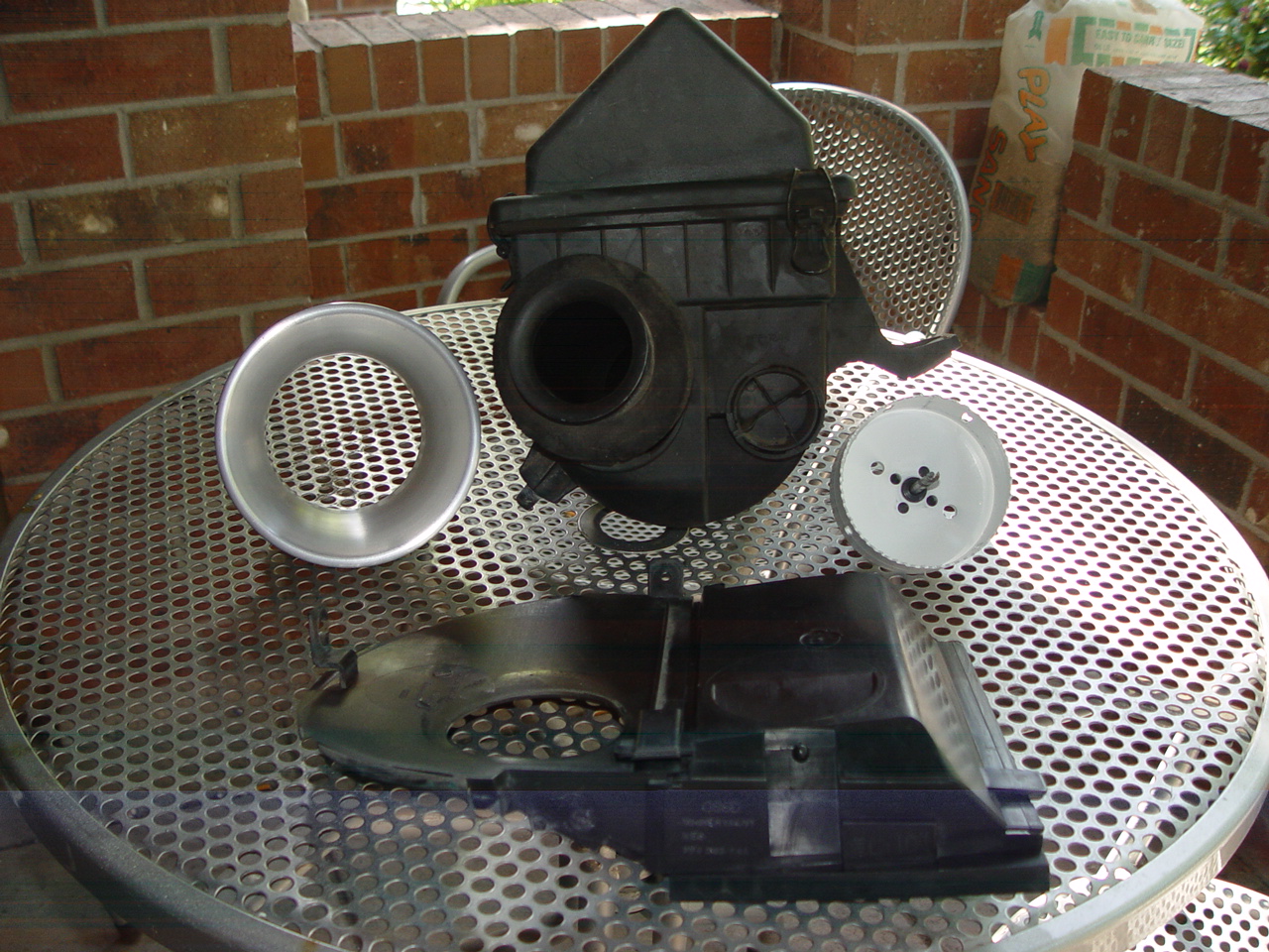
We'll start this workshop with a picture of the B4 airbox with it's OEM 2" ID cold air intake snorkel and the OEM backing plate which mates to the airbox intake snorkel on a stock car at the backing plate. The large foam collar around the back of the small velocity stack inlet is what seals the OEM velocity stack against the high pressure airbox backing plate allowing 100% of the intake charge to be fed a constant "mostly" clean and cold/cool air supply without introducing any engine compartment heat.
The small OEM velocity stack flared end goes into the high pressure air compartment and the foam collar presses against the compartment backing plate creating a "mostly" sealed compartment tho thee are small areas thru-out the compartment that can bleed off air. The new backing plate I'm building will be completely sealed off and should create some small "ram air" affect much like I did at this forum 5 or so years ago. Sadly I wont have anywhere near the surface area opening to work with that I did back in the B5/Ram Air workshop era but there are things I will be doing to get more frontal air into the compartment towards the end of this workshop.
While I'm specifically doing a B4 setup in this workshop, much of what I'm doing can be adapted to other induction systems so feel free to take what you can use and adapt it to your personal situation. There's no right/wrong in any of this regarding how much you will personally benefit from it. The goal is a higher flowing airbox and "any" measure of improvement will perform better than what you had before you adopted anything you read here to your personal situation. So feel free to follow along and use as little or much of this as you're comfy with.
Pic above also shows the 4" diameter hole saw I'll be using to cut the 4" diameter hole that the 6" inlet by 4" outlet velocity stack I'll be integrating into this airbox.
Pic 2: Instructions on where to prep
airbox for hole cutting...
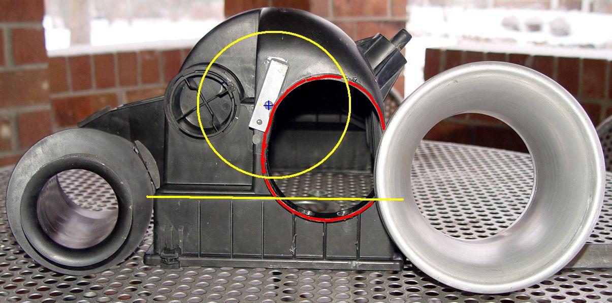
This pic shows approximatly where to cut the airbox if using a hole saw. You could also do this with a jig saw or even a die grinder if on a tight budget. If not using a hole saw simply lay out your lines on masking tape placed across the airbox face and use an architect's compass.
If using a hole saw it's crucial that you stabilize the the hole saw drill guide by first drilling thru a piece of 1/8" thick metal before sawing. The epoxy that piece of metal to the airbox face and allow to fully cure before drilling. If this is not done you risk having the hole saw catch an edge with it's teeth and it will pull the drill guide out of it's center cutting plastic as it goes. If that happens you're in DEEP cah-cah and now need to start considering one of the other cutting/grinding options mentioned above. But done right the hole saw gives the fastest, cleanest, most "round" hole and is quickest results hands down taking all of about 10 seconds!
The red line in above pic shows the OEM airbox flange that needs to be ground flush before using a hole saw or you'll have insufficient depth with the hole saw to get all the way thru the various depths and contours in the airbox. And if not using a hole saw it still needs to be ground flush with the airbox face anyway as you'll see in later pics where it will stick out like a sore thumb if not ground flush.
The yellow circle is the diameter approximation that you'll be cutting. The small strip of aluminum is the drill guide stabilizer I've epoxied to this airbox after finding it's center.
The horizontal yellow line is something you DO NOT want to cut above as that represents the airbox filter medium's lower paper pleat line. If you cut above that line (towards the top of the airbox) your filter pleats will be squished/compressed against any part of the velocity stack that enters the airbox. That will also contribute to a bad sealing area around the filter element's top gasket. You can get as close to that area as you want but DO NOT cross the yellow line!!
Pic 3: Now it's gonna get ugly for a
couple of updates...
Once the hole is cut the entire airbox lower half along with the unattached VS needs to be installed in the car to help figure out "exactly" where the VS needs to be adhered to and integrated with the airbox. This is a "fiddly/fidgety" task that is many things, however "fun" should NOT be counted among them. I cannot be of much help here since my new airbox rear compartment lid will be a one-off custom part. You'll need to figure out "your" alignment based on "your" car.
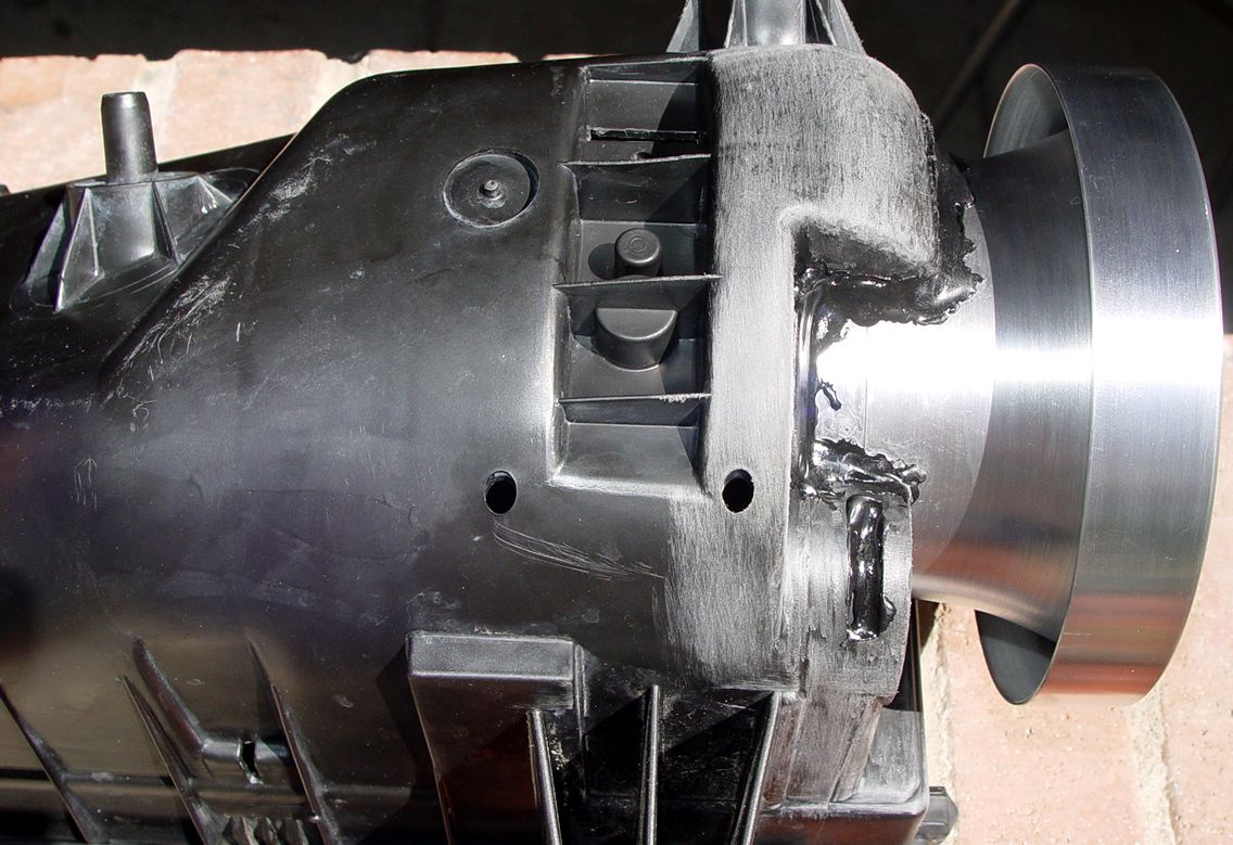
Essentially you just need to get the VS oriented and aligned how you want it then somehow temporarily adhere it there until you can get more adhesive on it when it's back out of the car. I chose Polyamide hot glue as it's what I use to seal the spherical bearings in my Pro-Mounts. It's as close to epoxy as you can get with a hot melt adhesive, horribly expensive and a PITA to find. But any "contractor grade" hot glue would work just fine. Basically 2-3 little 1/8" dabs of hot glue is all it takes to hold the VS in place very rigidly until you can get it out of the car and apply more. I prefer this to epoxy putty because it sets in under a minute so it's very easy to keep perfectly aligned by hand for that length of time while the hot glue sets up. It also precludes having to hold it with some other method while working. Once out of the car I can run a longer bead of the Polyamide adhesive to give a more solid/rigid set to it and the airbox. I just don't have the heart to use screws/bolts on this VS after all the time I spent making it as pretty and functionally efficient as it is today.
But the hot glue is not the structural adhesive that I'll be using to retain the VS within the airbox. That's reserved for expandable urethane foam that will be applied soon as this is posted. I'll post pics of that later after it "skins over" and is set up enough to handle. But I won't be able to start sanding on if for fully 24 hours unless I accelerate it by throwing it in my curing oven.
You can see the black Polyamide in this pic as well as the sanding I've done to give all adhesive products a tenacious "tooth" to the airbox.
Pic 4: Inside airbox prior to urethane
foam...
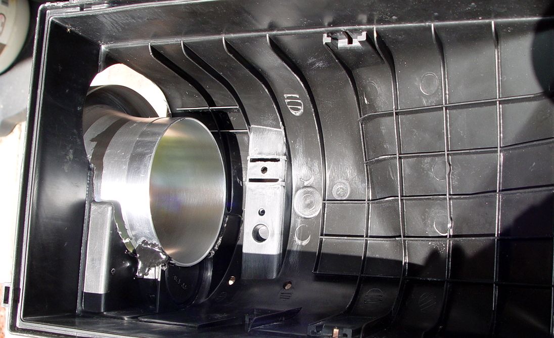
This pic shows the smooth/non-ribbed filter pleat area all around the top of the lower airbox half that should not be cut into or have anything sitting higher than lest it squish your filter pleats and "un-do" much of what this workshop is about.
The huge gaping hole is from the OEM inlet snorkel and will be covered/sealed with expandable urethane foam filler. That filler is bright orange with a 2,000F temp rating which isn't needed but it's all I could put my hands on without running another errand. Steer FAR away from any "latex" expandable foam fillers if going this route!! When I'm done I will be able to stand on my VS once the urethene is fully cured. I would literally pull the face off the airbox inlet side before being able to separate the VS from the airbox. The uethane is "that" good!
I'll post more when I get to the next stopping point but this is probably the last post for a few hours.