Our cars use a
hot wire anemometer mass air flow sensor to measure the air flow going to the engine. This info is used by the ECU to decide how much fuel to inject by controlling the fuel injector duty pressure (as related to the boost pressure). Here is what Audi says about the MAF:

Here is what the small inner sampling tube and hot-wire look like (note the dirt in the tube):
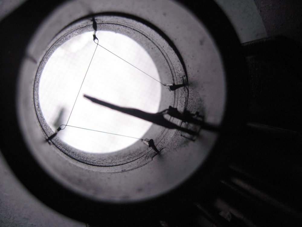
Photo courtesy of deephouse (Brian C).(Taken with "Macro" on)
As far as I can tell, the mass air flow sensor (MAF) for the ABY S2 is the same as that for the RR Urq, the 3B S2 and 200 20vt and the UrS4 and UrS6 (all same PN 034133471K). The RS2 MAF is similar but different (wider opening screens) (PN 034133471N). (See photo below: 471K on he left, RS2 471N on the right). In both cases, when the engine is shut off, the ECU sends a current to the MAF hotwire that is enough to burn off the crud that has accumulated. (NOTE: PN update the 471N RS2 MAF is the same as a 944 turbo MAF PN 951.606.125.02 (also Bosch 0280213017)). Scarman (Tom G) found some interesting info about Bosch remanned MAF PNs
HERE
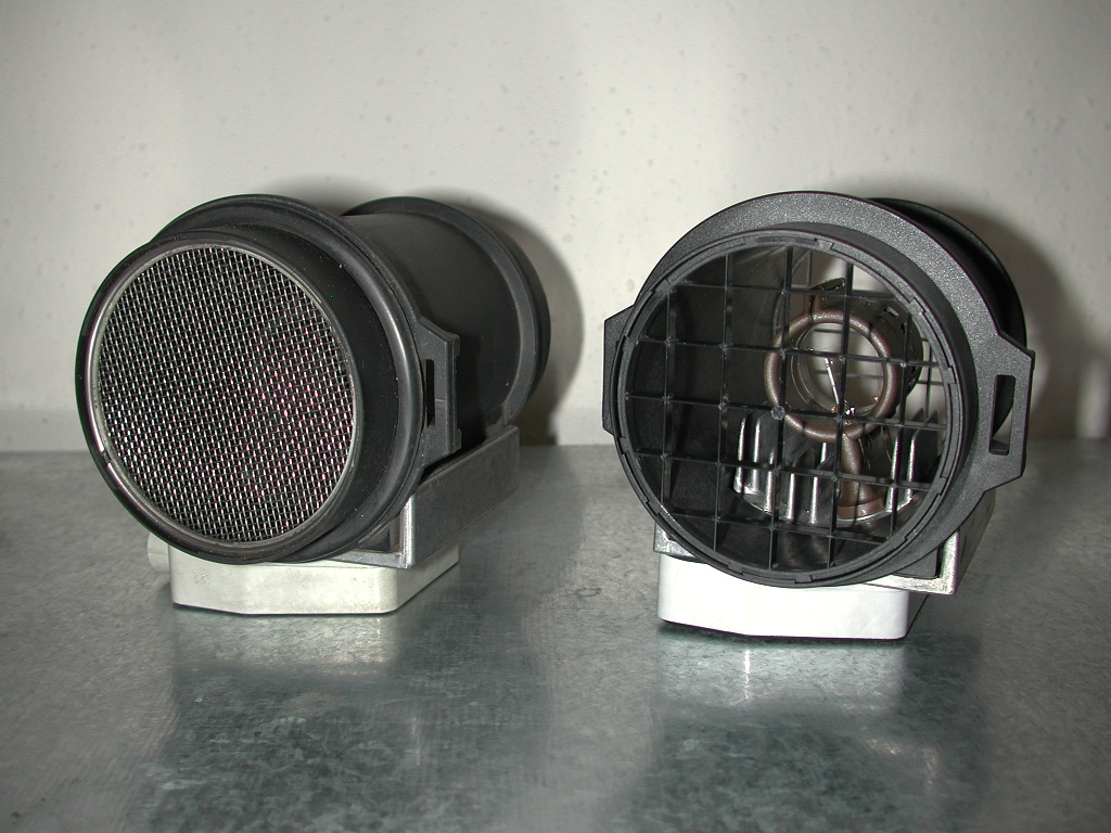
Image courtesy of Jimmy Pribble
Airflow of the RS2 MAF is superior to the 471K, as pointed out in a post by Manx:
Click here to see what Manx found
Removing the inlet screen on the 471K will improve air flow but could lead to turbulence across the hot wire (and therefore bad signals). Not too much is said about the rear 471K screen.
The electrical signals from the 471K and the RS2 MAFs are similar. Close enough that, in the last few years, tuners have been tuning using the 471K, even with RS2 and above turbos. BUT remember, the airflow is still less with the 471K with the screens intact.
Here is what Cody Payne found out about the 471K and RS2 471N output voltages:

The MAF connector sometimes develops some corrosion and may need to be cleaned and Stabilant 22 added (to keep the corrosion at bay). If there is more trouble, you might want to replace the connector.
As with all Audi electrical devices, the power is brought to the device in a female flat pin connector that mates up (no pun intended) with the male pins that stick out of the device that is to be powered, in this case, the MAF. In the case of the MAF, it's a flat six pin female connector or "terminal housing" in Audispeak. Here is a look at a dirty connector on the MAF:
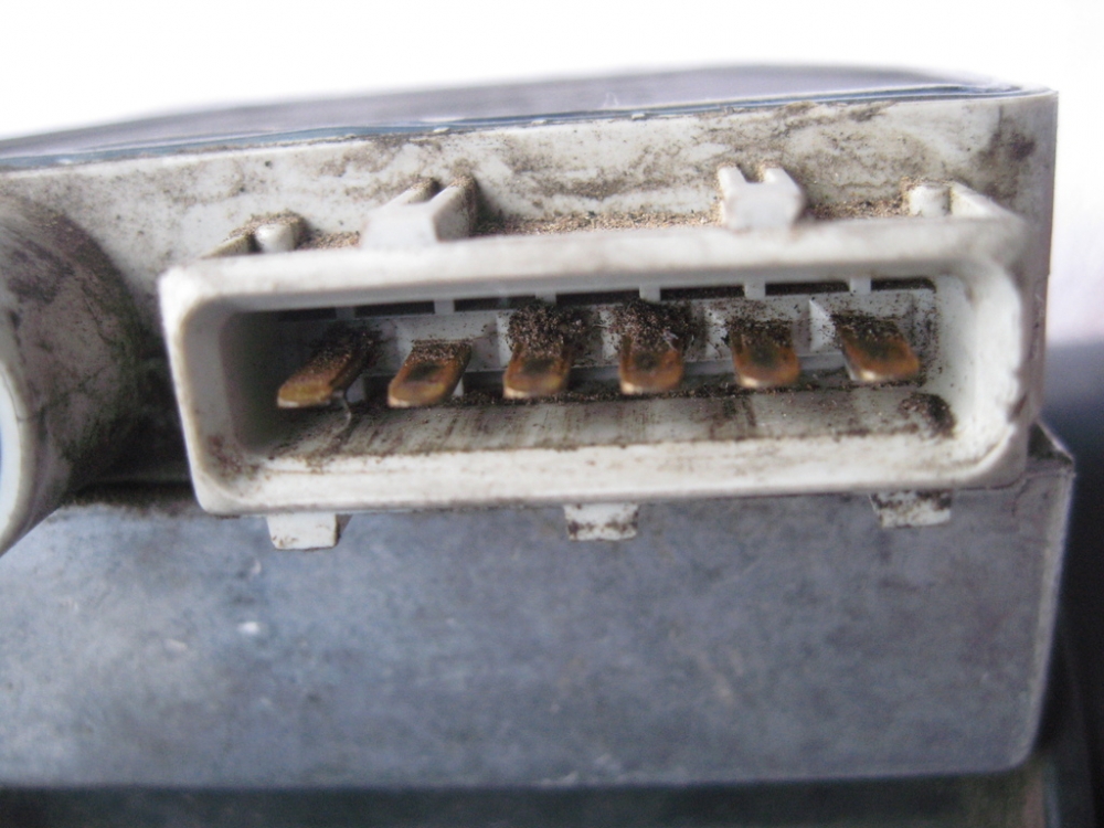
Photo courtesy of deephouse (Brian C)
The PN for this six pin connector was originally 022 906 233 A. However, at some point, it was dropped and replaced by 025 906 238 B. The female pins for this connector typically come two on a yellow covered pig tail wire. The PN for these female connectors is 000 979 133 or 133A for the 1 mm wide pins or 225 or 225 A for the 2.5 mm wide pins. The "A" is for the gold-plated version (slightly more costly but likely the ones you want if corrosion is a problem).
NOTE: Another MAF problem is sometimes the male pins of the MAF miss the "target" on the female pins and end up pushing the female pins backwards, out of the harness MAF connector, as shown here for the similar throttle/idle switch connector:

If that is the case, all sorts of wierd missing happens (poor connection) and maybe even a 4411 code (i.e. injector No. 1 fault). The solution is to clean the connection (male and female pins) and then after reconnecting, pushing the female pins individiually, from the back of the connector towards the MAF to make sure they are properly mated with the male pins.
For the MAF connector the female pins are only in positions 1 through 5; No. 6 the one at the left end of the connector is empty (in the throttle position connector (in the photo above) No. 6 is filled and 5 is empty). For the MAF harness connector, the five pins are as follows:
Pin 1 = Brown with red stripe, goes to a ground (16) (on the cylinder head (cam) cover)
Pin 2 = Red with black stripe, goes to pin T26/55 in the ECU
Pin 3 = Green with white stripe, goes to pin T7/55 in the ECU
Pin 4 = Green with purple (violet) stripe, goes to pin T25/55 in the ECU
Pin 5 = Black with red stripe, connects to the fuel injector harness.
This will be on the exam.


 -
-  -
-