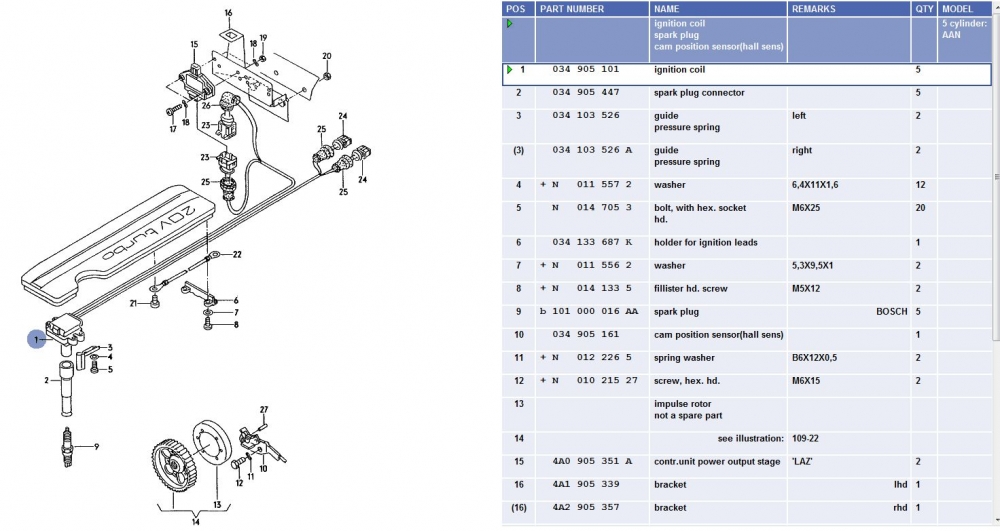
I created this for the 1.8t coil pack instructions back in 2005. It is useful if you are still running the OE ignitions system, as shown here with the coil on plugs, the short boot connectors and the power output stages:
The original "civilian" 20VT I5 engine was the 3B rated at about 217 hp. This engine used a single coil, a distributor with a Hall effect sender and five sparkplug wires, one each for each of the five spark plugs. The engine engineers at Audi figured out that IF they provided each cylinder with its own coil, then the engine could make more horsepower (about 10 DIN hp more), bringing the nominal flywheel hp up from 217 to 227 hp (220 to 230 DIN hp). The trouble was they needed some kind of computer controlled switch to fire these coils in the correct order and at the correct time. Enter the POWER output stage or POS.
The AAN has two three channel power output stages (POS) units (PN 4A0905351A)mounted on the firewall (they were developed for six cylinder wasted-spark cars). Here's what VAG says about them:
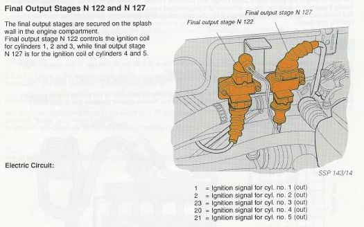
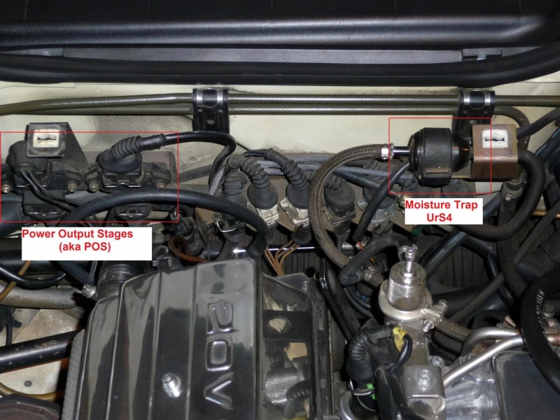
See photo below for location (more info below the photo - Photo courtesy of Jeff S.):
As shown above devices are named N122 and N127. However "N122" and "N127" are just device names. They are identical. Both have 4 pin inputs (for 3 ECU inputs and 1 ground) and 3 pin outputs (for up to 3 coils). What is important that for the POS with the four wires coming into it from the ECU, you have the 3 wire lead to the coils connected to it (3 = 1,2,3). Likewise, the POS with the 3 wires coming to it from the ECU needs to be connected to the 2 wire lead to the coils (2 = 4,5).
The primary coils wires are black and are labled with their cylinder number. They are NOT the input TO the coils as often thought. They are actually the outlet for the current flow FROM the primary side of the coils. The power feed TO the primary side of the coils are yellow wires that come from the two white three pin connectors on the metal connector rack on the firewall. The ignition-switched 12 V power is fed from the these connectors to the primary side of the coils. However, the primary side of the coil has no ground so normally there is no current flow or, as a result, no spark. The ground is actually through the POS unit and pin 2/4 and its white-striped brown (BR/W) wire.
The VAG study guide POS wiring diagram and the Motronic ECU input/output diagram, show a very "schematic" version of this:
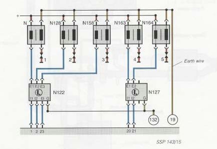
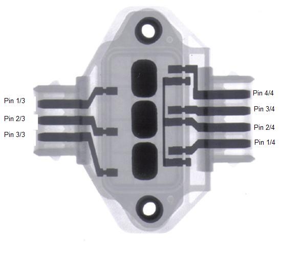
If you were to believe the above schematic, you would think the ground was on Pin 4/4 on the ECU harness side and that the 1/4 and 1/3 pins (and 2/4 and 2/3 and 3/4 and 3/3 pins) run through the POSs directly. In fact this is wrong, the ground is on Pin 2/4 and the input output pins do not flow through as the diagram suggests. In fact, it is like this, with the pins crossing (1/4 to 3/3, 3/4 to 2/3 and 4/4 to 1/3) (the dark rounded rectangles are the switching transistors)
The ECU (engine management computer, with the aid of a signal from the crank position sensor (and cam position sensor during starting)), sends a 5 VDC (or so) signal to the respective channel on one of the POS's, Inside the POSs, there three transitorized swithes that, when triggered by the ECU's 5 V signal, send the 12 V current FROM the Primary coil to ground (through pin 2/4). With the "gate" open for current flow through the primary coil, this rush of current in the primary coil, "excites" the secondary coil which in turn produces a high voltage current that rushes to the nearest way out, which in this case is the spark plug.
The POSs fail because inside there are some very fine wires that seem to get brittle with age and/or heat. These wires break or crack, resulting in poor or intermittent current flow. We call that missing or hesitation.
Internally, in the POSs, as discussed above, Pin 1/4 connects to Pin 3/3, Pin 2/4 is a ground (brown with white stripe that eventually goes to the intake manifold), Pin 3/4 connects to Pin 2/3 and Pin 4/4 connects to Pin 1/3. Rember that. Draw a diagram if needed.
For POS N122, a green wire with a white stripe comes from Pin 1 of 55 in the ECU connector, representing Cylinder No. 1, and connects to Pin 4/4. The corresponding wire from the primary coils is connected to Pin 1/3 on the three pin side. A violet (purple) wire with a white stripe comes from Pin 2 of 55 in the ECU connector and connects to Pin 3/4 of N122, representing Cylinder No. 2. The corresponding wire from the primary coils is connected to Pin 2/3 on the three pin side. Pin 2/4 is the Brown with white stripe primary coil ground wire. A black with grey stripe wire comes from pin 23 of 55 in the ECU connector and goes to Pin 1/4 of the N122 POS for cylinder No. 3. The corresponding primary coil wire goes to Pin 3/3.
Got that? Good, because that comes from the Bentley wiring diagram (pg. 24/X52), Scott Mockry's website (for the ECU pinout) and the convenient X-ray of a POS shown above (now annotated to show the pin numbers).
Link to the X-rayed POS article
Now it gets tricky. For the second POS, N 127, the Bentley is wrong. I will tell you the truth but you can easily comfirm what I say below by checking the wires yourself.
First, the ECU feed for cylinder No. 4 is a Black with yellow stripe from pin 20 in the 55 pin ECU connector. For No. 5, it is a black with white stripe from Pin 21/55 in the ECU connector. The tricky bit is the Bentley mislabled what happens to these two wires when they connect to the four pin side of the POS. The BK/Y (Cylinder no. 4) wire connects to Pin 4/4 (which is correct in the Bentley) BUT the Bentley shows the primary coil wire from Cylinder 5 going to Pin 1/3 on the three pin side. That is WRONG. Its primary coil no. 4 that goes to Pin 1/3 and primary coil no. 5 goes to 2/3, which corresponds to the black with white stripe wire from ECU 21/55 going to Pin 3/4 on the four pin side of the N 127 POS. As always Pin 2/4 on N 127 is the POS-switched ground for the primary coils.
IIf you were paying attention, Pin 1/4 and Pin 3/3 on N 127 are normally not used. This is the spare channel (the POSs were developed for six-cylinder wasted-spark cars). This allows the potential to swap connectors and/or pins when one POS channel fails. For example, if you confirm that the POS for cylinder 4 is dead, you can move the wire in BK/Y for cylinder 4 in the four position POS input connector from 4/4 to the empty 1/4 position and then move the cylinder 4 coil wire 1/3 to the empty 3/3 position on the POS output connector.
When swapping the pins, pull the rubber boot back, away from the connector housing. Then push the purple pin holder out of the back of the black (or brown) connector housing. The purple pin holder has a little flap on one side. Lift it up. That will free up one retaining tangs of the female pin. Use a bent paper clip to push the tang on the other side of the pin in and then extract the pin out the back of the purple pin holder. Place the pin in the un-used position and close the purple pin-retaining flap. Load the purple pin holder back into the black (or brown) connector housing and return the rubber boot to its normal position. Re-attach the connector to the proper POS. Swap the ECU harness pins accordingly.
HERE IS A PICTORAL HOW-TO ON PIN SWAPPING
This 4 or 5 pin swap is is a one time fix. When the second channel fails, e.g. cylinder 5, you're done. You will need to buy a new POS. As stated above the PN for the OE Bosch POS is 4A0905351A. In jamb, you can use a brown Hitachi or Beru from a wasted-spark V6, PN 4A0905351 (no "A").
This will be on the exam.


 -
-  -
- 