A common thing for people to want to do is replace the stock stereo with something that will play CDs. This does not
necessarily mean that the stock speakers need to be replaced, but that is of course entirely up to you.
If you are replacing the head unit, there are several questions to ask yourself. First, do you want a stereo with
red or orange illumination to match the rest of the console? Do you want a stereo that will drive your current
speakers? If it will drive your current speakers then it needs line level (not amplified) outputs for the rear
speakers.
When I replaced my stereo, I purchased a Blaupunkt Sydney head unit and CDC-A08 10-disc changer. The advantage here is that
the stock stereo system was a Blaupunkt unit so most of the plugs were the same. I had to get an adapter to add the CD
changer, swap two wires, and that was it.
But enough about me. Assuming you just want to see how to plug in whatever you bought, here are some useful pinouts for the
stock stereo system:
 |
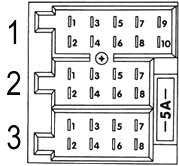
This is the block of connectors on the back of the stock stereo. This is a standard Blaupunkt layout, or
at least it was for several years. It goes like this:
Connector 1: 10 point, red
- Data (for in-dash radio frequency display)
- Clock (for in-dash radio frequency display)
- Enable (for in-dash radio frequency display)
- Not connected
- Ground
- Not connected
- Not connected
- Line-level output to right rear speaker
- Not connected
- Line-level output to left rear speaker
Connector 2: 8 point, brown
- Not connected
- Not connected
- Right front speaker (+) (amplified output)
- Right front speaker (-) (amplified output)
- Left front speaker (+) (amplified output)
- Left front speaker (-) (amplified output)
- Not connected
- Not connected
Connector 3: 8 point, black
- Vehicle speed signal
- Not connected
- Not connected
- Ignition lock (for security code and flashing LED)
- Switched battery positive for antenna amplifier/power antenna
- Radio illumination
- Constant battery positive
- Constant battery negative
|
|
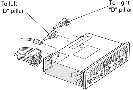
| This is the layout of the connectors on the back of the stock radio. Several Audi models had the radio
antenna integrated with the rear window defroster, and that antenna was split into two parts. Each part of
the antenna (one for AM and FM signals, the other just for FM) had its own antenna amplifier, in one side of
the D pillar that the rear windshield sits on. |
 |
|
 |
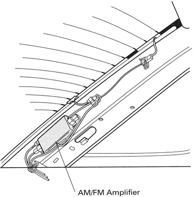
In the left D pillar is the AM/FM amplifier. This connects to the top three lines of the rear window
defroster, which do not actually defrost -- they are only for the antenna. They are made to look like defroster
lines so that they blend in, but you'll notice that if the defroster is on the top three rows don't do anything.
This is why. |
|
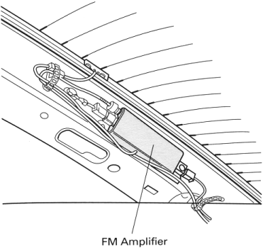
| In the other D pillar is the FM amplifier. This connects to the rest of the defroster element (which actually
defrosts). The stock head unit, when tuned to an FM station, will automagically use whichever antenna is picking
up the signal better, and switch inputs if necessary. If your new stereo does not support more than one antenna,
don't use this one if you want to pick up AM stations. |
 |
|
Other useful notes about the stock stereo system:
- Front speaker ratings: 15 Watts continuous, 18 Watts peak at 4 ohms
- Front speaker frequency range: 50Hz - 17,000Hz
- Rear woofer (bass speaker) ratings: 15 Watts continuous, 25 Watts peak at 4 ohms
- Rear woofer frequency range: 60Hz - 17,000Hz
- Rear tweeter (treble speaker) ratings: 15 Watts continuous at 4 ohms
- Rear tweeter frequency range: 5,000Hz - 20,000Hz
|


