Hi-flow Airbox Workshop Part 2
continued...
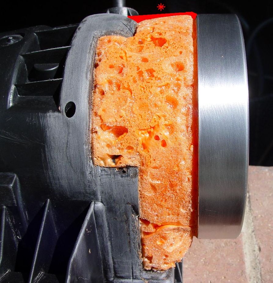
In this pic you can see how I've cut a "V-Channel" between the foam and both the velocity stack as well as the airbox. Reason is that the 3M putty I'll be using to seal the foam doesn't like to end/terminate against a dissimilar material with a tissue-thin feathered edge. Therefore by using the v-channel at both ends of the putty where it meets the VS and airbox this method allows for a much thicker layer or the putty. This allows the putty to be much thicker, more rigid and dimensionally stable to ward off any hairline separation that would otherwise form where the putty terminates at both the airbox and the VS.
In top of pic I've placed an asteisk showing how a cross section of what I'm trying to achieve with this layer of putty. How it will be thin across the large spans of urethane foam but much thicker where it mates to the dissimilar materials of the aluminum VS and the plastic airbox.
The entire series of pics with this series of posts are related to cutting, shaping, sanding the urethane foam in perparation for the urethane filler/sealer putty.
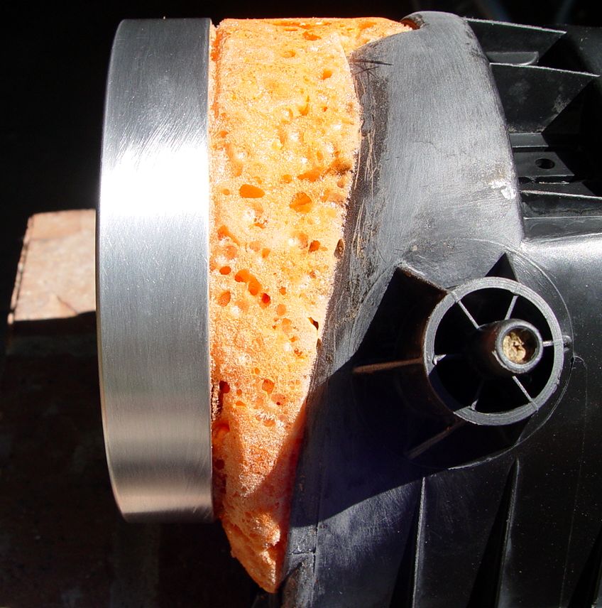
Pic 2: Opposite side V-channel...
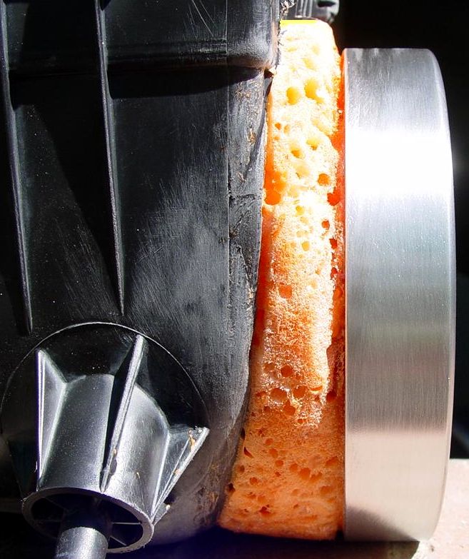
Pic 3: Airbox front side/velocity stack V-channel...
Pic 4: Inside airbox at velocity stack...
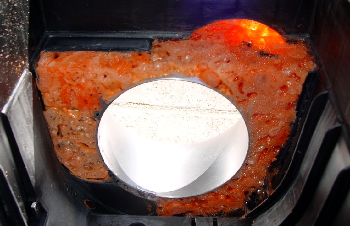
No V-channeling required internally as this area cannot be seen. Any hairline separations that appear internally between urethane putty and airbox walls or bottom will be repaired with a silicone sealer from a tube or caulking gun and cured in an oven so none of the silicone vapors ever get to the engines electronics like MAF and O2 sensors.
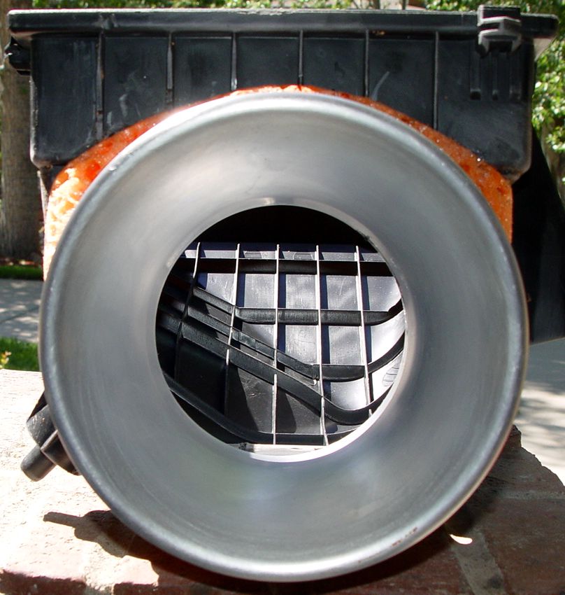
Pic 5: Airbox velocity stack inlet viewed
from front...
Next update will cover the 3M urethane putty.